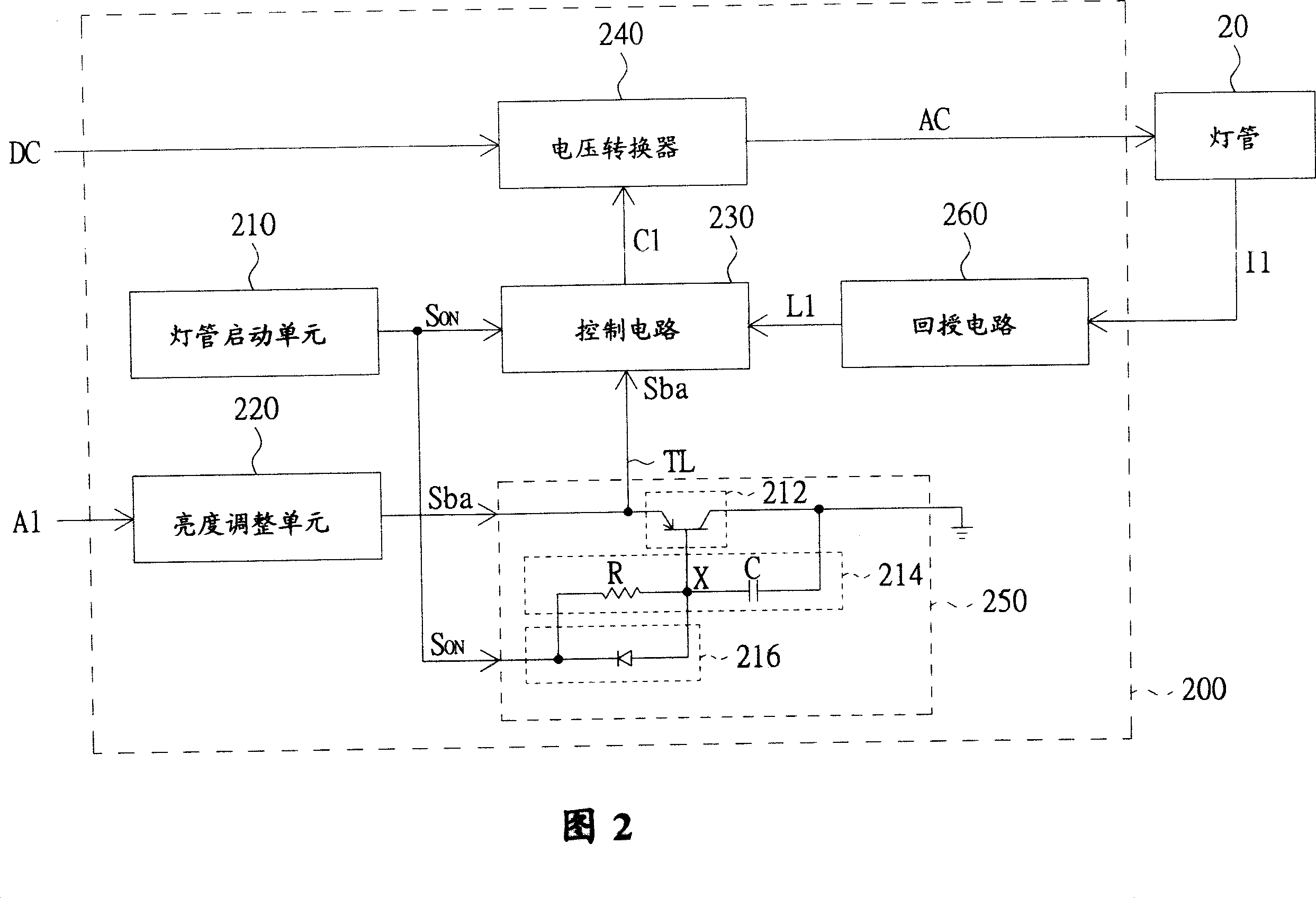
[0016] Please refer to FIG. 2 , which is a circuit block diagram of a cold cathode tube power supply system according to a preferred embodiment of the present invention. The cold cathode tube power supply system 200 includes a brightness adjustment unit 220 , a control circuit 230 , a voltage converter 240 and a brightness control unit 250 . The brightness adjustment unit 220 is used to output the brightness adjustment signal Sba, the brightness adjustment signal Sba is transmitted to the control circuit 230 through the brightness control unit 250, and the brightness control unit 250 also receives the lighting signal S ON.
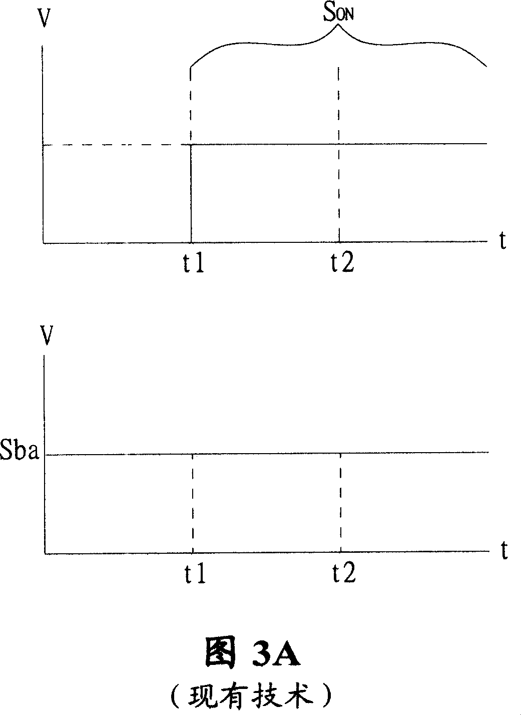
[0017] Please refer to Fig. 3B at the same time, which shows the lighting signal S of the preferred embodiment of the present invention ON and the waveform diagram of the brightness adjustment signal Sba. The brightness adjustment signal Sba includes a lower brightness signal and a higher brightness signal, that is, a first brightness signal S1 and a second brightness signal S2 respectively. When the brightness control unit 250 detects the lighting signal S ON , the brightness control unit 250 changes the brightness adjustment signal Sba to the first brightness signal S1 and maintains it for a predetermined period of time. After a predetermined period of time, the brightness control unit 250 restores the brightness adjustment signal Sba to the second brightness signal S2.
[0018] That is, the brightness control unit 250 outputs the first brightness signal S1 as the brightness adjustment signal Sba within a predetermined period of time. After a predetermined period of time, the brightness adjustment unit 220 may output the second brightness signal S2 as the brightness adjustment signal Sba according to the brightness adjustment signal A1 set by the user. The control circuit 230 outputs a power control signal C1 according to the first brightness signal S1 and the second brightness signal S2. The voltage converter 240 outputs an AC voltage AC according to the power control signal C1 to drive the lamp 20 . The lamp tube 20 is, for example, a cold cathode lamp tube.
[0019] During the predetermined period, the control circuit 230 outputs the power control signal C1 according to the first brightness signal S1, and after the predetermined period, the control circuit 230 outputs the power control signal C1 according to the second brightness signal S2. Wherein, the first brightness signal S1 is substantially smaller than the second brightness signal S2.
[0020] Preferably, the control circuit 230 is an OZ960 or OZ964 series pulse width modulation (Pulse Width Modulator, PWM) controller. Taking the PWM controller of the model OZ964 as an example, the brightness adjustment unit 220 is electrically connected to the ninth pin of the PWM controller of the model OZ964 through the brightness control unit 250, so that the first brightness signal S1 and the second brightness signal S2 are transmitted thereto. Pin 9. The PWM controller of model OZ964 senses the voltage of pin 9 to monitor the magnitude of the current flowing through the light tube 20 . By changing the voltage value received by pin 9, the brightness of the lamp can be set.
[0021] As shown in FIG. 2 , the power supply system 200 further includes a lamp starting unit 210 and a feedback circuit 260 . The lamp starting unit 210 is used to output the lighting signal S ON To start the lamp tube 20 . The feedback circuit 260 is used to receive the feedback current I1 output by the lamp tube 20 , and generate a feedback voltage L1 according to the feedback current I1 to output to the control circuit 230 . The control circuit 230 is also used to receive the lighting signal S ON.
[0022] In addition, the brightness control unit 250 includes a switch 212 and a charging circuit 214 . The charging circuit 214 is coupled (or connected) to the lamp starting unit 210 to receive the lighting signal S ON. The switch 212 is coupled to the charging circuit 214 and the brightness adjustment unit 220 and used for controlling the change of the brightness adjustment signal Sba. When the brightness control unit 250 receives or detects the lighting signal S ON , the charging circuit 214 receives the lighting signal S with a high voltage level ON to charge. Upon receiving a high voltage level lighting signal S ON From then on until the charging circuit 214 finishes charging, the switch 212 is turned on, so that the brightness adjustment signal Sba changes to the first brightness signal S1. After the charging circuit 214 finishes charging, the switch 212 is turned off, so that the brightness adjustment signal Sba is changed into the second brightness signal S2 and output to the control circuit 230 .
[0023] Preferably, the charging circuit 214 includes a resistor R and a capacitor C, and the resistor R and the capacitor C are electrically connected to the node X. The switch 212 is a PNP bipolar junction transistor (bipolar junction transistor), and the PNP bipolar junction transistor has a base, an emitter and a collector. Wherein, the base is coupled (connected) to the node X between the resistor R and the capacitor C, and the emitter is coupled to a specific pin (for example, the above-mentioned 9th pin) of the control circuit for setting the brightness of the lamp tube. The electrodes are coupled to ground voltage. When the switch 212 is turned on, the ground voltage is output through the turned on switch 212 to reduce the voltage level of the brightness adjustment signal Sba, so that the brightness control unit 250 outputs the ground voltage as the first brightness signal S1. After the switch 212 is turned off, the ground voltage cannot be output through the switch 212 , so the brightness adjustment signal Sba is output as the second brightness signal S2 and bypassed by the brightness control unit 250 to the control circuit 230 .
[0024] In addition, the brightness control unit 250 further includes a discharge circuit 246 . The discharge circuit 246 is, for example, a diode, and one end of the diode is coupled (connected) to the lamp starting unit 210 to receive the lighting signal S ON , and the other end is coupled to the node X of the charging circuit 224 . After the cold cathode tube power starting system 200 is turned off, the charge of the charging circuit 224 is discharged through the diode.
[0025] As shown in Figure 3B, before the time point t1, the lighting signal S ON It is not input to the power supply system 200, so the power supply system 200 does not start the lamp tube 20, but outputs a low voltage, so the PNP bipolar junction transistor of the switch 212 is maintained in a conducting state, so no matter what the user does at the beginning It is set that the brightness adjustment signal Sba is maintained at the first brightness signal S1. At the moment of time t1, the lighting signal S ON Input to the power supply system 200 , so that the power supply system 200 activates the lamp tube 20 accordingly.
[0026]During the period from t1 to t2, the switch 212 is maintained in the on state, so the brightness adjustment signal Sba is still maintained at the first brightness signal S1, and the charging circuit 214 receives the lighting signal S with a high voltage level. ON to charge. Since the first brightness signal S1 is the ground voltage, it can ensure that the control circuit 230 receives the lighting signal S ON After the first luminance signal S1, its operating frequency will not be too high to make the operation of the power supply system 200 exceed the limit. Therefore, the control circuit 130 can control the power converter 240 to output the AC voltage AC, so that the lamp tube 20 can be turned on smoothly.
[0027] After a stable period of time after the start of the lamp tube, for example at time point t2, the charging circuit 214 has completed charging, so the switch 22 is therefore closed, and the brightness control unit 250 receives the second brightness signal S2 of the brightness adjustment signal Sba, and uses The second brightness signal S2 is output to the control circuit 230 in a bypass manner. The control circuit 230 receives the second brightness signal S2 and the lighting signal S ON The feedback voltage L1 is used to generate a power control signal C1, so that the brightness of the lamp 20 is increased to a value desired by the user.
[0028] The cold-cathode tube power supply system disclosed in the above embodiments of the present invention can also be regarded as a cold-cathode tube lighting device. After lighting, use the brightness control unit to provide a lower brightness signal to change the brightness of the lamp, that is, to change the load of the power supply system, so that the power supply system controls the circuit during the period when the AC voltage AC is converted from the starting voltage to the working voltage. In the process of converting the frequency of the power control signal C1 outputted by 230 correspondingly, the duty cycle will not exceed the normal working limit of the power supply system. After a short period (predetermined period) after the lamp is turned on, the brightness control unit provides a higher brightness signal, so that the brightness of the lamp is adjusted to a desired brightness of the user. The power supply system of the present invention can improve the problem that the power supply system of the cold cathode tube exceeds the working limit due to improper frequency conversion during the lighting process, so as to achieve the purpose of lighting the lamp smoothly.
[0029] In summary, although the present invention has been disclosed as above with a preferred embodiment, it is not intended to limit the present invention. Those skilled in the art of the present invention can make various changes and modifications without departing from the spirit and scope of the present invention. Therefore, the protection scope of the present invention should be defined by the appended claims.
[0030] Description of main component symbols
[0031] 10, 20: light tube
[0032] 100, 200: Power supply system for cold cathode tubes
[0033] 110, 240: voltage converter 120, 260: feedback circuit
[0034] 130, 230: control circuit 210: lamp start unit
[0035] 220: brightness adjustment unit 212: switch
[0036] 214: charging circuit 216: discharging circuit
[0037] 250: brightness control unit