Check patentability & draft patents in minutes with Patsnap Eureka AI!

Projection device

A projection device and image technology, applied in projection devices, optics, instruments, etc., can solve the problems of focal length planning and design of focusing elements, insufficient brightness, and no special setting of optical element distance, etc., to achieve good projection effect and sufficient brightness Effect

Active Publication Date: 2008-03-05
QUISDA CORP
View PDF0 Cites 3 Cited by
  • Summary
  • Abstract
  • Description
  • Claims
  • Application Information

AI Technical Summary

Problems solved by technology

However, in a general optical engine, the focal length of the focusing element is not designed as a whole, and the distance between the optical elements is not specially set
Therefore, in the process of designing the optical engine, various design pro

Method used


Image

  • Projection device
  • Projection device
  • Projection device

Examples


Example Embodiment

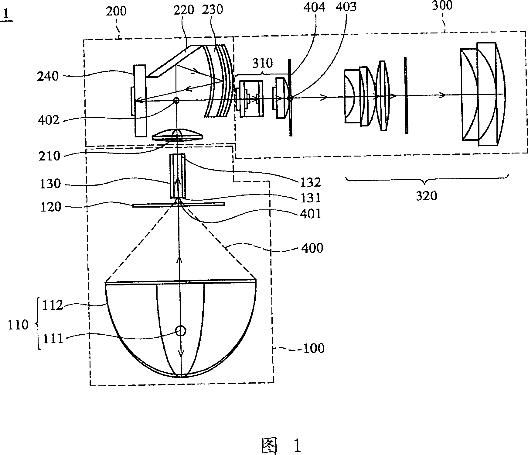
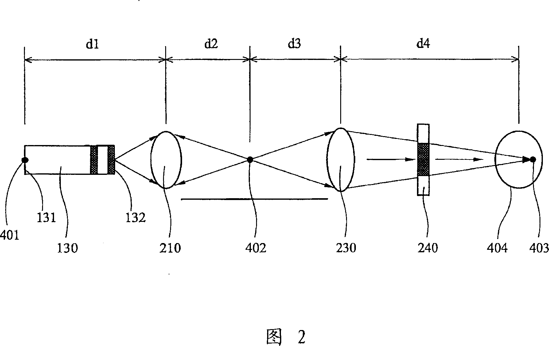
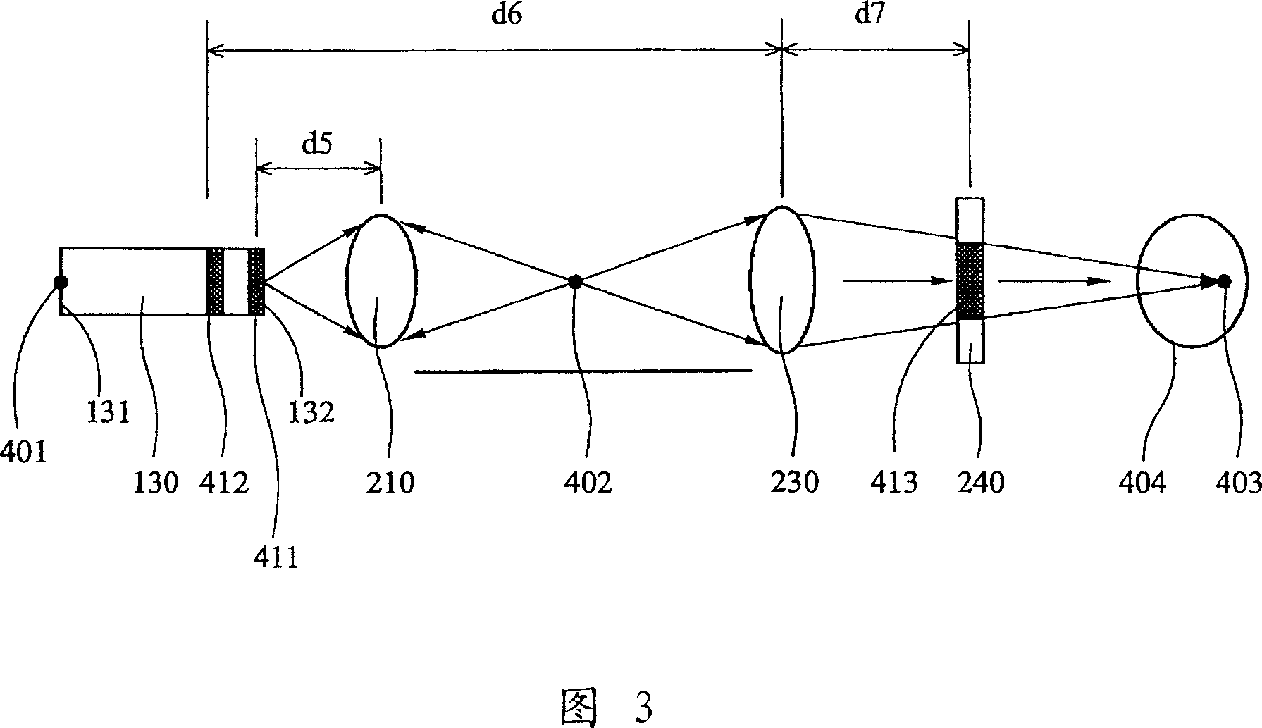
Referring to FIG. 1, it shows that the projection device 1 of the present invention includes a light source unit 100, an illumination unit 200 and an image unit 300. The light source unit 100 includes an ellipsoidal lamp 110, a color wheel 120, and a light guide element (light pipe) 130. The lighting unit 200 includes a first focusing element (relay lens) 210, a reflecting mirror 220, a second focusing element 230, and a micromirror element 240. The imaging unit 300 includes a first lens group 310 and a second lens group 320.

The ellipsoidal lamp 110 includes an integrated light source 111 and an ellipsoidal lampshade 112.

The volume light source 111 is arranged at the first focal point of the ellipsoidal lampshade 112 and provides a beam 400. The ellipsoidal lampshade 112 focuses the beam 400 on the second focal point of the ellipsoidal lampshade 112, that is, a first end 131 of the light guide element 130. The light beam 400 enters the lighting unit 200 from the ellipsoid lamp ...


PUM


Abstract

The invention comprises: light source unit, a light guide component, a first focus component, a second focus component, a micro lens component and an imaging unit. The light source unit is used for providing a beam which passes through the light guide component; the first focus component comprises a first focus length f1; the second focus component comprises a second focus length f2, and the beam enters into the second focus component from the first focus component; wherein, 2.0<F2/f1<3.6; the beam enters into the imaging unit through the second focus component and micro lens component.

Description

technical field The invention relates to a projection device, in particular to a projection device with small size and good projection effect. Background technique In the optical engine of a general projection device, the light beam will undergo multiple reflections after passing through the light guide to provide sufficient brightness and good image performance. At the same time, the image and the size of each optical element can be effectively controlled through multiple times of focusing, thereby reducing the overall size of the optical engine. However, in a general optical engine, the focal length of the focusing element is not planned and designed as a whole, and the distance between the optical elements is not specially set. Therefore, in the process of designing the optical engine, various poor designs such as poor projection effect, insufficient brightness, and dark bands on the edge often occur. In addition, if the design is simply considered only for the project...

Claims


Application Information

Patent Timeline
IPC IPC(8): G03B21/00G03B21/14
Inventor 林明坤
Owner QUISDA CORP
Features
  • R&D
  • Intellectual Property
  • Life Sciences
  • Materials
  • Tech Scout
  • Unparalleled Data Quality
  • Higher Quality Content
  • 60% Fewer Hallucinations
Learn More