

Image forming apparatus and developing agent cartridge
A developer cartridge and developer technology, applied in the fields of electric recording technology using charge pattern, equipment for electric recording technology using charge pattern, and electrography, can solve problems such as toner leakage and achieve reliable miniaturization Effect
- Summary
- Abstract
- Description
- Claims
- Application Information
AI Technical Summary
Problems solved by technology
Method used
Image

Examples
no. 1 example
[0077] 1. The overall structure of the laser printer
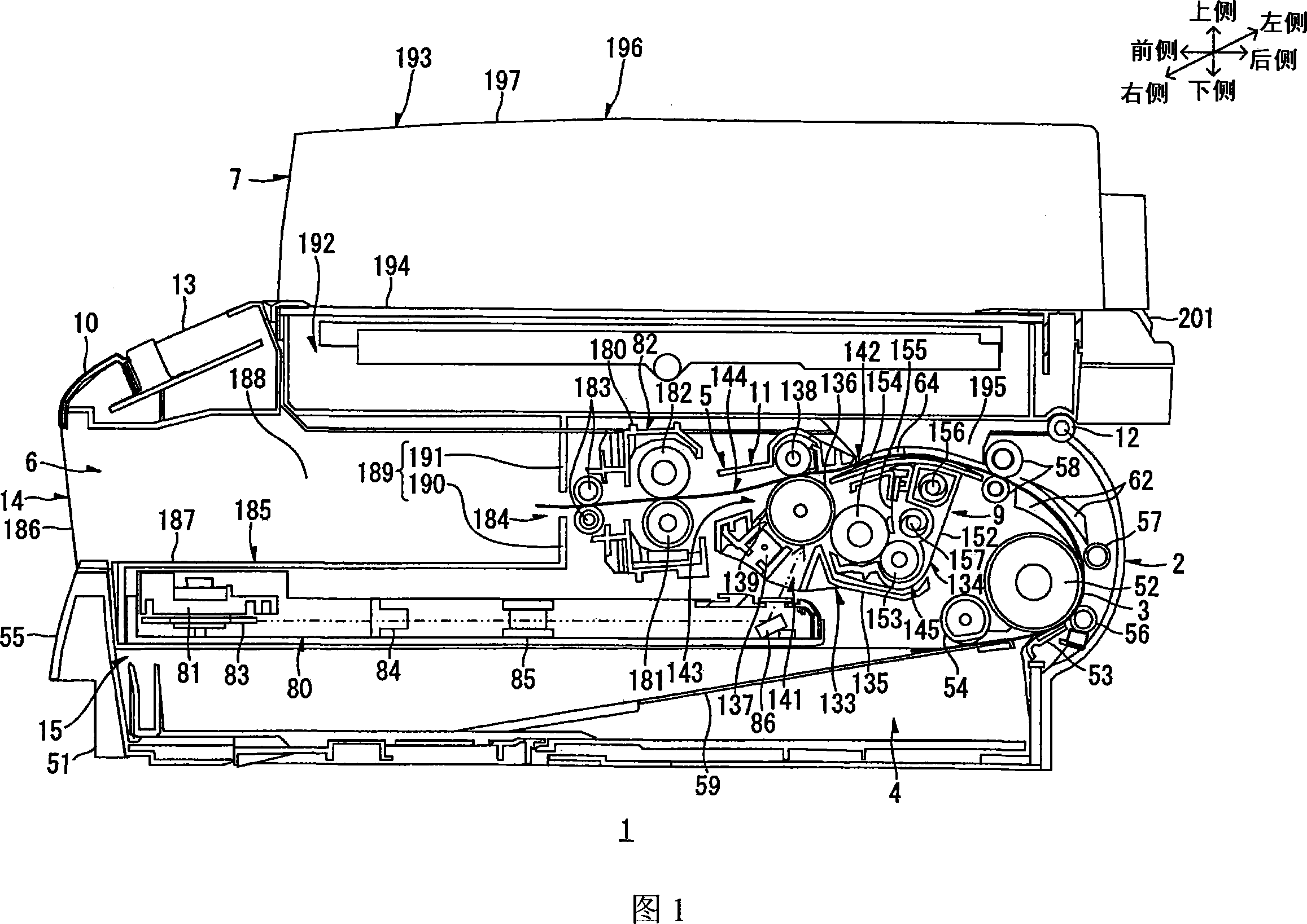
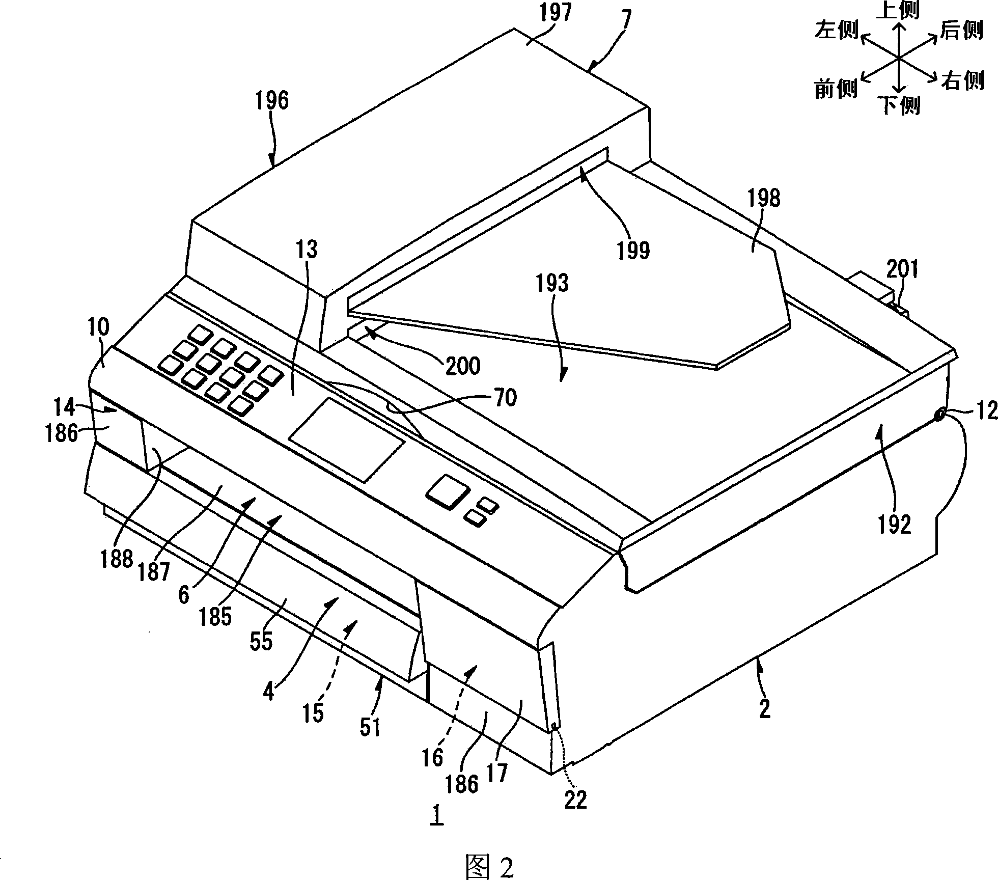
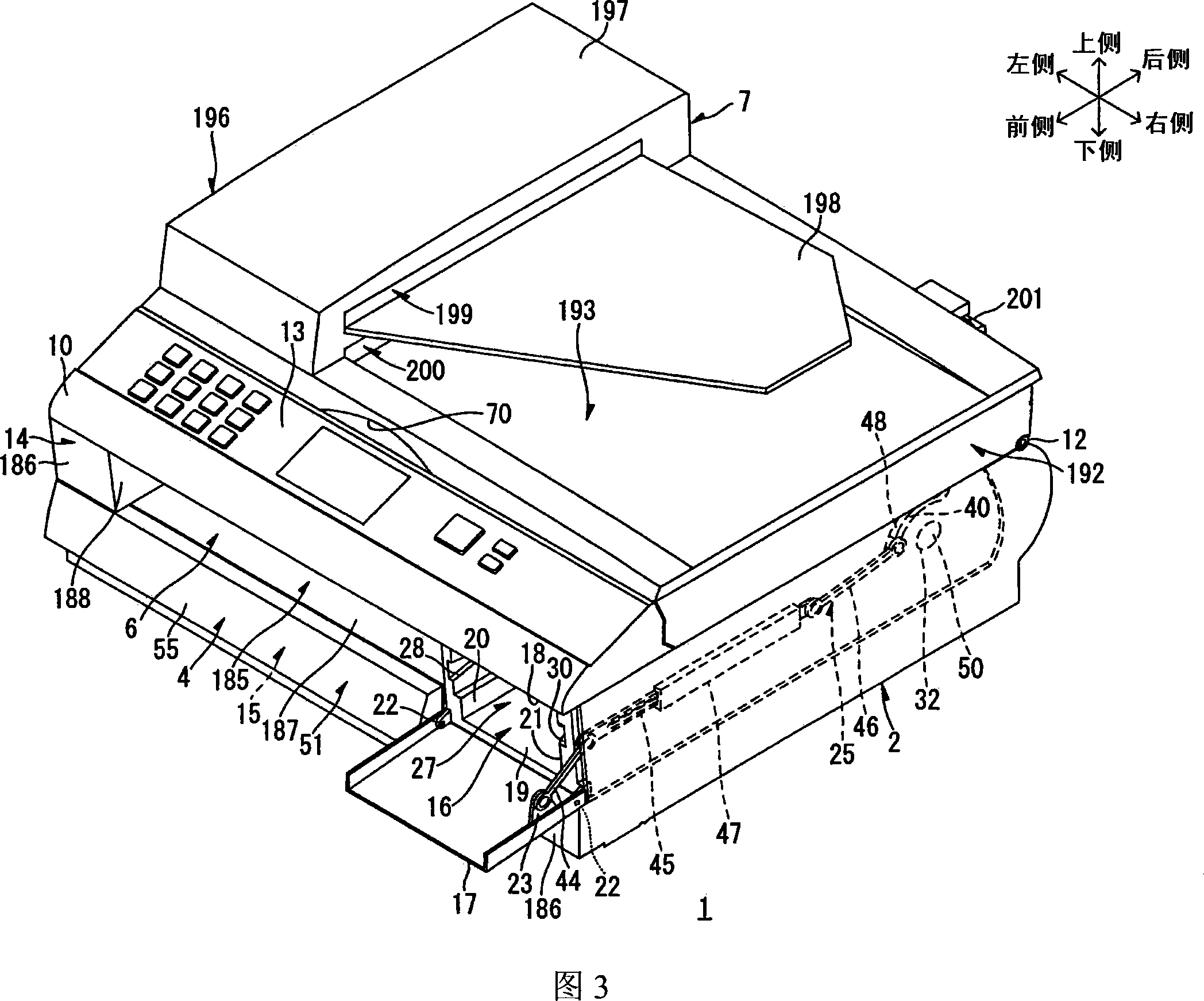
[0078] 1 shows a side cross-sectional view of a main part of an illustrative aspect of a laser printer as an example of an image forming apparatus of one or more aspects of the present invention, and the figure shows a mode in which the scanning unit described later is closed. Fig. 2 shows a perspective view of the laser printer shown in Fig. 1 viewed obliquely from above on its right front side. Fig. 3 shows the state in which the cover in Fig. 2 is in the cover open position.
[0079] As shown in FIG. 1, the laser printer 1 is a multifunctional machine, and includes a main body casing 2 as an example of a casing, a paper feeding portion 4 and an image forming portion 5 housed in the main body casing 2, and formed in the main body casing 2. The discharging section 6 in the main body housing 2 and the scanning unit 7 as an example of an image reading unit are provided above the main body housing 2.
[0080] The paper feeding s...
no. 2 example
[0307] In the above embodiment, the operation panel 13 is provided on the upper wall 10 of the main body housing 2. However, it can also be set on the document board 192. In this case, the operation panel 13 is moved together with the scanning unit 7 so that the processing section mounting port 11 can be opened widely, thereby making it easier to replace the toner cartridge 8.
[0308] In the above-described embodiment, the processing section 9 as a whole includes the drum section 133 and the developing section 134, and is detachably mounted to the main body housing 2. In addition, in the laser printer 1, for example, in a state where the drum portion 133 is installed in the main body casing 2, the developing portion 134 may be detachably installed to the drum portion 133.
[0309] In the foregoing embodiment, the paper feed tray 51 can be detachably installed in the main body casing 2. However, the paper feed tray 51 may be integrally formed with the main body casing 2. In this c...
no. 3 example
[0312] (1) Toner cartridge
[0313]Figure 15 shows a perspective view of the toner cartridge viewed obliquely from above on the rear left side according to the third embodiment: (a) illustrates the state in which the developer accommodating portion is in the closed position of the cartridge shutter; (b) illustrates the developer The accommodating part is in a state where the box gate is open. Figure 16 shows a right side cross-sectional view of the toner cartridge according to the third embodiment: (a) illustrates the state in which the developer accommodating portion is in the closed position of the cartridge shutter; (b) illustrates the state in which the developer accommodating portion is in the open position of the cartridge shutter . Figure 17 shows a right side view of the toner cartridge according to the third embodiment: (a) illustrates the state in which the developer accommodating portion is in the closed position of the cartridge shutter; (b) illustrates the state in wh...
PUM
 Abstract
Description
Claims
Application Information