
Collector shoe device

A technology of collector boots and boots, which is applied in the direction of current collectors, power collectors, electric vehicles, etc., can solve the problems of increased inertial mass and failure to ensure good contact, so as to ensure contact and improve followability Effect

Inactive Publication Date: 2008-04-23
CENTRAL JAPAN RAILWAY COMPANY
View PDF1 Cites 12 Cited by
  • Summary
  • Abstract
  • Description
  • Claims
  • Application Information

AI Technical Summary

Problems solved by technology

Therefore, similarly to the above-mentioned structure shown in FIG. 19 , there is a possibility that the inertial mass increases and the contactability at both ends of the slider 7a cannot be ensured satisfactorily.

Method used


Image

  • Collector shoe device
  • Collector shoe device
  • Collector shoe device

Examples


Embodiment

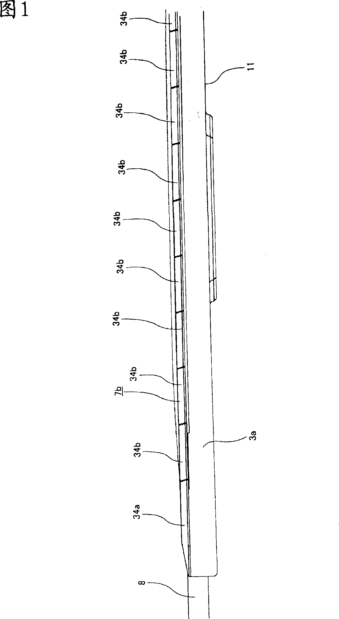
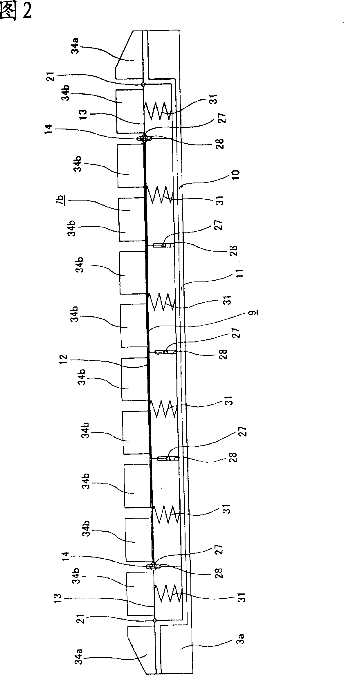
[0079] 1-18 illustrate embodiments of the present invention. The collector shoe device of this embodiment has a shoe body 3 a, a slider support body 9 and a slider 7 b.

[0080] Among them, the shoe body 3 a is formed into a boat shape by chamfering an aluminum alloy material or by die casting, and is supported on an upper end portion of a pantograph frame (not shown) across the width direction of the railway vehicle. Between these boots 3a and the pantograph frame, there is provided a link mechanism not shown, which is widely known in the technical field of pantograph devices for railway vehicles in the past, and the connection between the pantograph frame and the above-mentioned pantograph frame. It doesn't matter if it is upright or down, the upper surface of the boot 3a is parallel to the roof surface of the vehicle.

[0081] In addition, the above-mentioned skateboard support body 9 is accommodated in the above-mentioned shoe body 3 a via a support frame 10 manufactured ...


PUM


Abstract

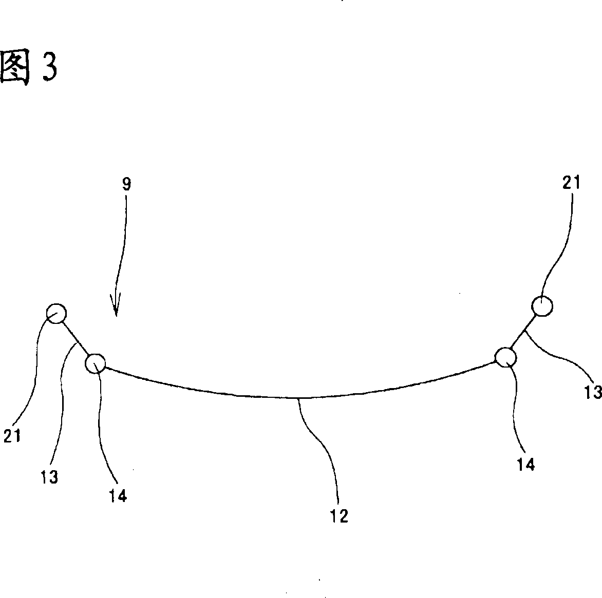
A collector head device capable of well retaining a contact between overhead wires and a contact strip (7b) over the contact strip (7b) in the longitudinal direction. The contact strip (7b) formed of contact strip elements (34a) and (34b) divided in the lateral direction of a vehicle is supported on the upper surface of a contact strip support body (9). Based on a load applied to a center support member (12) forming the slide strip support body (9) due to the contact between the overhead wires and the contact strip (7b), the center support member (12) is formed to be elastically deformed in a recessed shape downward in the longitudinal direction. Also, both end parts of the center support member (12) are swingably supported on a head body (3a) through end support members (13). As a result, even if the overhead wires are positioned at the longitudinal both end parts of the contact strip (7b), the contact strip (7b) is allowed to follow up the fluctuation of the overhead wires based on the elastic deformation of the center support member (12) and the lifting of the center support member (12).

Description

technical field [0001] The present invention relates to an improvement of a collector shoe device installed on the roof of a high-speed railway vehicle such as a Shinkansen in order to introduce electric power from a overhead wire, and aims to improve the followability of the slider to the overhead wire. A device that ensures the contact performance (the ability to maintain a proper contact state) between these wires and the slide. Background technique [0002] The collector shoe is supported by a pantograph above the roof of the rolling stock, and electric power is introduced from overhead wires. That is, a slider made of a conductive material such as sintered metal supported on the upper surface of the collector shoe is elastically pressed against the lower edge of the overhead wire, and electric power is introduced into the vehicle from the overhead wire. Among such pantograph and collector shoe devices, the devices used for high-speed vehicles such as the Shinkansen are...

Claims


Application Information

Patent Timeline
Patent Type & Authority Applications(China)
IPC IPC(8): B60L5/08
CPCB60L5/08B60L2200/26B60L5/20
Inventor 冲本文男成濑功中仓康喜寺田泰隆山中信生四釜敏男藤原润一北泽贤一
Owner CENTRAL JAPAN RAILWAY COMPANY
Learn More