Steroscopic display and manufacturing method thereof

A technology of a stereoscopic display and a manufacturing method, which is applied to stereoscopic systems, static indicators, instruments, etc., can solve the problems of limited observer positions and high dependence of stereoscopic image viewing angles, and improve display quality, save manufacturing costs, and increase viewing angles Effect

Inactive Publication Date: 2008-05-21
AU OPTRONICS CORP
View PDF0 Cites 76 Cited by
  • Summary
  • Abstract
  • Description
  • Claims
  • Application Information

AI Technical Summary

Problems solved by technology

[0005] Although the above-mentioned technology can make the observer wear the polarized glasses to display the stereoscopic image smoothly, but for the observer, when wearing the polarized glasses

Method used


Image

  • Steroscopic display and manufacturing method thereof
  • Steroscopic display and manufacturing method thereof
  • Steroscopic display and manufacturing method thereof

Examples


no. 1 example

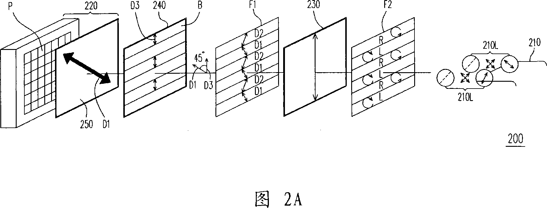
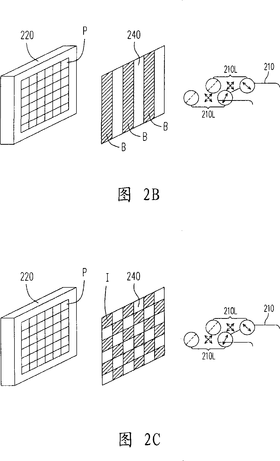
[0059] FIG. 2A is a schematic diagram of the first embodiment of the stereoscopic display of the present invention. Please refer to FIG. 2A , the stereoscopic display 200 is suitable for the viewer to watch while wearing circular polarized glasses 210, wherein the circular polarized glasses 210 have two circular polarized lenses 210L with left-handed and right-handed polarized characteristics, and the circular polarized lens 210L is as As shown in Figure 2A, it can be regarded as a combination of a quarter-wave plate and a linear polarizer. In addition, the stereoscopic display 200 includes a flat display panel 220 , a quarter-wave plate 230 and a patterned half-wave plate 240 . In this embodiment, the patterned half-wave plate 240 is disposed on the flat display panel 220, and the quarter-wave plate 230 is disposed on the patterned half-wave plate 240, and the patterned half-wave plate 240 is located in a quarter between the wave plate 230 and the flat display panel 220 . T...

no. 2 example

[0071] FIG. 5 is a schematic diagram of a second embodiment of the stereoscopic display of the present invention. Referring to FIG. 5 , the stereoscopic display 400 is similar to the stereoscopic display 200 described in the first embodiment, but the configuration positions of the quarter-wave plate 230 and the patterned half-wave plate 240 of the stereoscopic display 400 are different from the stereoscopic display 200 . The quarter-wave plate 230 of the stereoscopic display 400 is disposed on the flat display panel 220, and the patterned half-wave plate 240 is disposed on the quarter-wave plate 230, and the quarter-wave plate 230 is located on the patterned half-wave plate 230. between the sheet 240 and the flat display panel 220 .

[0072]In this embodiment, the flat display panel 220 has an upper polarizer 250, wherein the optical axis of the upper polarizer 250 extends in a direction D1, so that the flat display panel 220 is suitable for displaying a linearly polarized ima...


PUM


Abstract

The present invention discloses a stereoscopic display, which is suitable for watching by an observer wearing a spectacle. The spectacle is provided with two cycle partial lenses with different polarization characteristics. The stereoscopic display comprises a flat display panel, a quarter wave plate and a nano-pattern half-wave plate. The flat display panel is provided with a plurality of pixels which are arranged in array and is suitable for displaying a partial line pattern. The quarter wave plate is arranged between the flat display panel and the spectacle. The nano-pattern half-wave plate is arranged between the flat display panel and the spectacle. The nano-pattern half-wave plate is corresponded to the part of the pixel. The present invention also provides a manufacturing method for the stereoscopic display. The nano-pattern half-wave plate of the present invention is provided with different phase delays in different areas. The quarter wave plate is used for transforming the line partial pattern to the cycle partial pattern. So the observer can see the stereoscopic display effect with low visual angle dependency. The present invention uses a single distribution direction for integrating the quarter wave plate and the nano-pattern half-wave plate, which can reduce the working complexity.

Description

technical field [0001] The invention relates to a display, and in particular to a stereoscopic display capable of providing images with different polarization directions to different regions of a liquid crystal display panel. Background technique [0002] With the advancement and development of science and technology, people's enjoyment of material life and spiritual level has always only increased but never decreased. On a spiritual level, in this era of rapid technological change, people hope to realize unrestrained imagination through display devices to achieve immersive effects; therefore, how to make display devices present three-dimensional images or images has become a modern The goal that display device technology is eager to achieve. [0003] In terms of appearance, stereoscopic display technologies can be broadly classified into stereoscopic, in which viewers need to wear specially designed glasses, and auto-stereoscopic, in which viewers directly watch with naked...

Claims


Application Information

Patent Timeline
IPC IPC(8): G02B27/26G02F1/133G02F1/1337G02F1/13363G02F1/1333G09F9/00H04N13/00G02B30/25
Inventor 叶碧纯郑岳世胡至仁
Owner AU OPTRONICS CORP
Why Eureka
Try Eureka