
Image forming apparatus

An image and fixing component technology, which is applied in the direction of electric recording process applying charge pattern, equipment of electric recording process applying charge pattern, electric recording technique, etc. Wear dispersion, easy swing effect

Inactive Publication Date: 2011-02-09
FUJIFILM BUSINESS INNOVATION CORP
View PDF2 Cites 0 Cited by
  • Summary
  • Abstract
  • Description
  • Claims
  • Application Information

AI Technical Summary

Problems solved by technology

This mark or wear can then cause image defects such as irregularities in the fixed image

Method used


Image

  • Image forming apparatus
  • Image forming apparatus
  • Image forming apparatus

Examples


Embodiment Construction

[0024] Embodiments of the present invention will be described below with reference to the accompanying drawings.

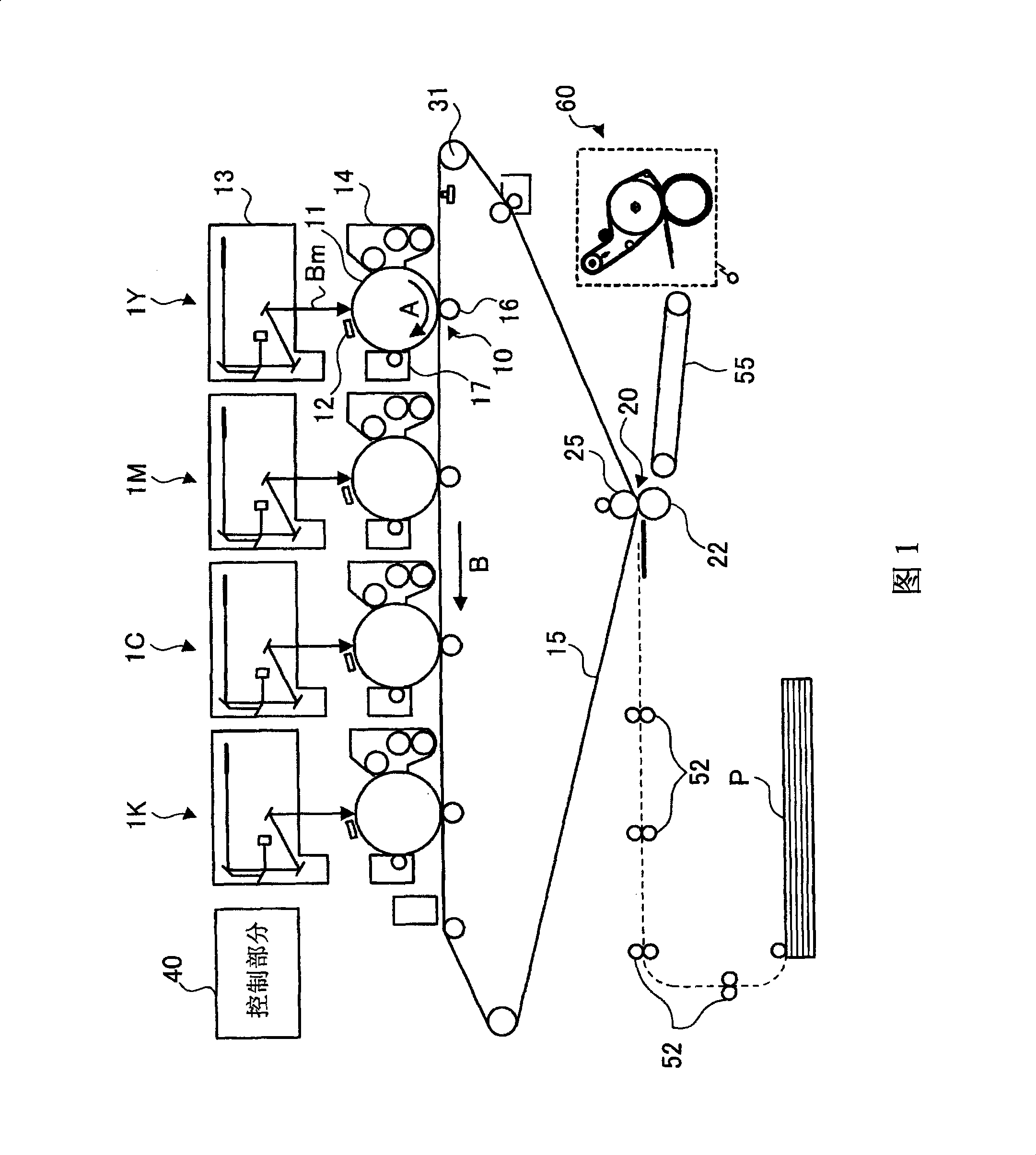
[0025] figure 1 is a schematic diagram showing the configuration of an image forming apparatus to which the present invention is applied. This image forming apparatus is an intermediate transfer type image forming apparatus generally called a tandem image forming apparatus. In this image forming apparatus, a plurality of image forming units 1Y, 1M, 1C, and 1K are formed, and toner images of various color components are formed in the image forming units by an electrophotographic method. In addition, in the image forming units 1Y, 1M, 1C, 1K, respectively, primary transfer portions 10 are provided in which the toner images of the respective color components are sequentially transferred onto the intermediate transfer belt 15 ( one transfer).

[0026] Further, in this image forming apparatus, there is provided a secondary transfer portion 20 in which the superimpos...


PUM


Abstract

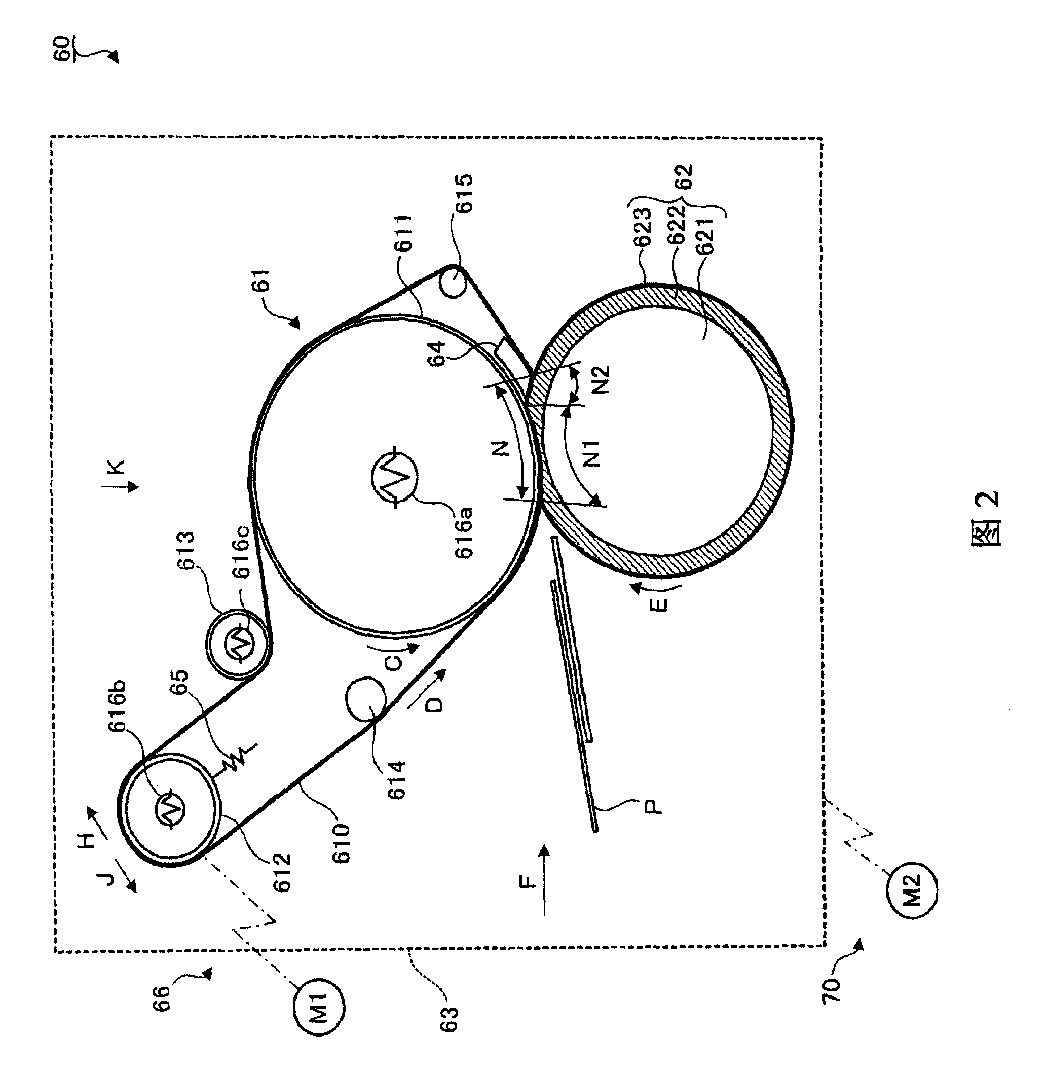
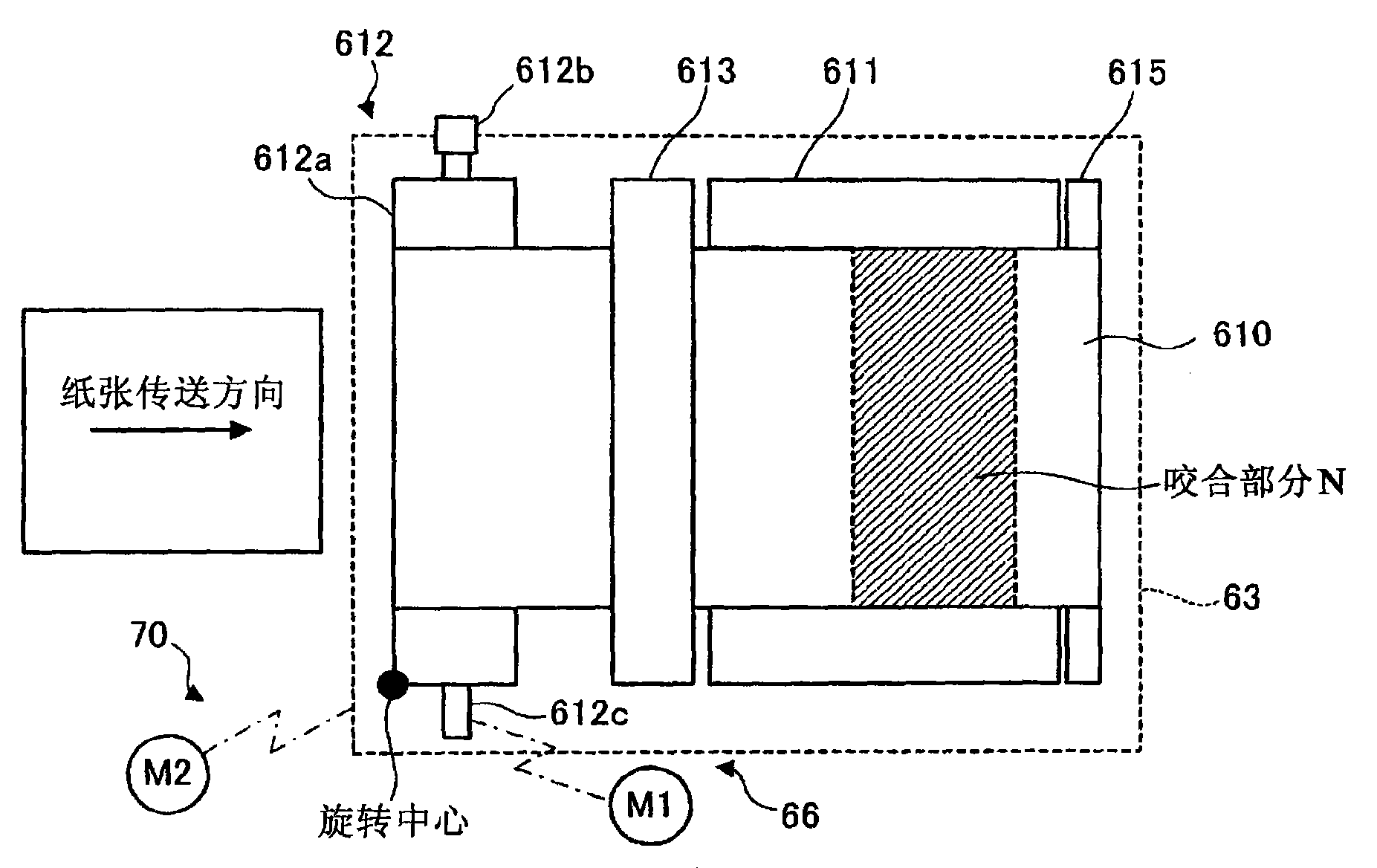
An image forming apparatus, includes: a first fusing member provided rotatably; a second fusing member disposed rotatably in press contact with the first fusing member, so as to define, together with the first fusing member therebetween, a nip section through which a recording material which holds an image thereon is to be passed; and a changing unit that changes an angle formed by the nip section and a transport direction of the recording material which is passed through the nip section.

Description

technical field [0001] The present invention relates to image forming apparatuses such as copiers and printers. Background technique [0002] In image forming apparatuses such as copiers and printers, for example, there are sometimes cases where a fixing unit is provided in the apparatus in which heat and pressure are applied to a recording material holding an image such as a toner image, The image thus held is thereby fixed on the recording material. As for a fixing unit like this, for example, there is a known fixing unit in which fixing members such as a roller member or a belt member are brought into pressure contact with each other so that recording materials on which an image is held are brought into pressure contact with each other through the fixing members. area, thereby fixing the retained image on the recording material (for example, see JP-A-3-133871 and JP-A-2003-5566). Contents of the invention [0003] Incidentally, when a recording material passes through...

Claims


Application Information

Patent Timeline
Patent Type & Authority Patents(China)
IPC IPC(8): G03G15/20G03G15/00
CPCG03G15/2085G03G2215/2022G03G15/2028
Inventor 吉野大典宫田敏行
Owner FUJIFILM BUSINESS INNOVATION CORP
Learn More