Golf Free Swing Measurement and Analysis System

a measurement and analysis system technology, applied in the field of golf free swing measurement and analysis system, can solve the problems of churchill failing to contemplate using rssi measurements, no prior art approaches contemplate a mobile system with sensors attached to the club head, and no computational algorithms involving multi-lever mechanics, etc., and achieve significant memory and usb connectivity

Inactive Publication Date: 2014-03-13
GOLF IMPACT
View PDF1 Cites 15 Cited by
  • Summary
  • Abstract
  • Description
  • Claims
  • Application Information

AI Technical Summary

Benefits of technology

[0023]An alternate embodiment of this invention contemplates a similar module without the RF communication circuitry and the addition of significantly more memory and USB connectivity. This alternate embodiment can store many swings of data and then at a later time, the module can be plugged directly into to a USB laptop port for analysis of each swing.

Problems solved by technology

However, none of these prior art approaches contemplate a mobile system with sensors attached to the club head and use receiver signal strength measurements to correlate time line measurements with the spatial domain for the non-linear travel path of the club head during a golf swing.
However, he does not contemplate the computational algorithms involving the multi-lever mechanics of a golf club swing required to solve for all the angles of motion of the club head during the swing with a varying swing radius.
Churchill fails to contemplate using RSSI measurements without the use of directional sectorized antennas in combination with sensors measurements analysis applied to a movable object with non-linear travel.
The prior art disclosures fail to teach a golf free swing analysis system that measures receiver signal strength at the club head that defines a swing time line of the non-linear club head travel path for the entire swing that is associated and referenced to the spatial domain.

Method used


Image

  • Golf Free Swing Measurement and Analysis System
  • Golf Free Swing Measurement and Analysis System
  • Golf Free Swing Measurement and Analysis System

Examples


first embodiment

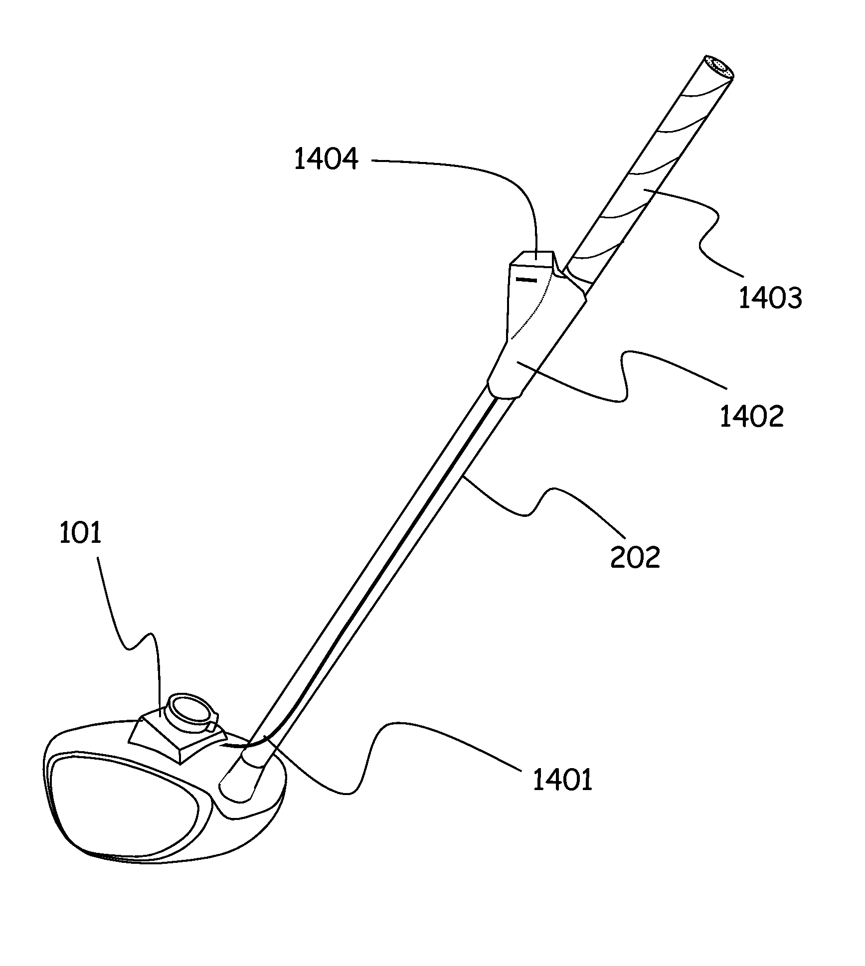
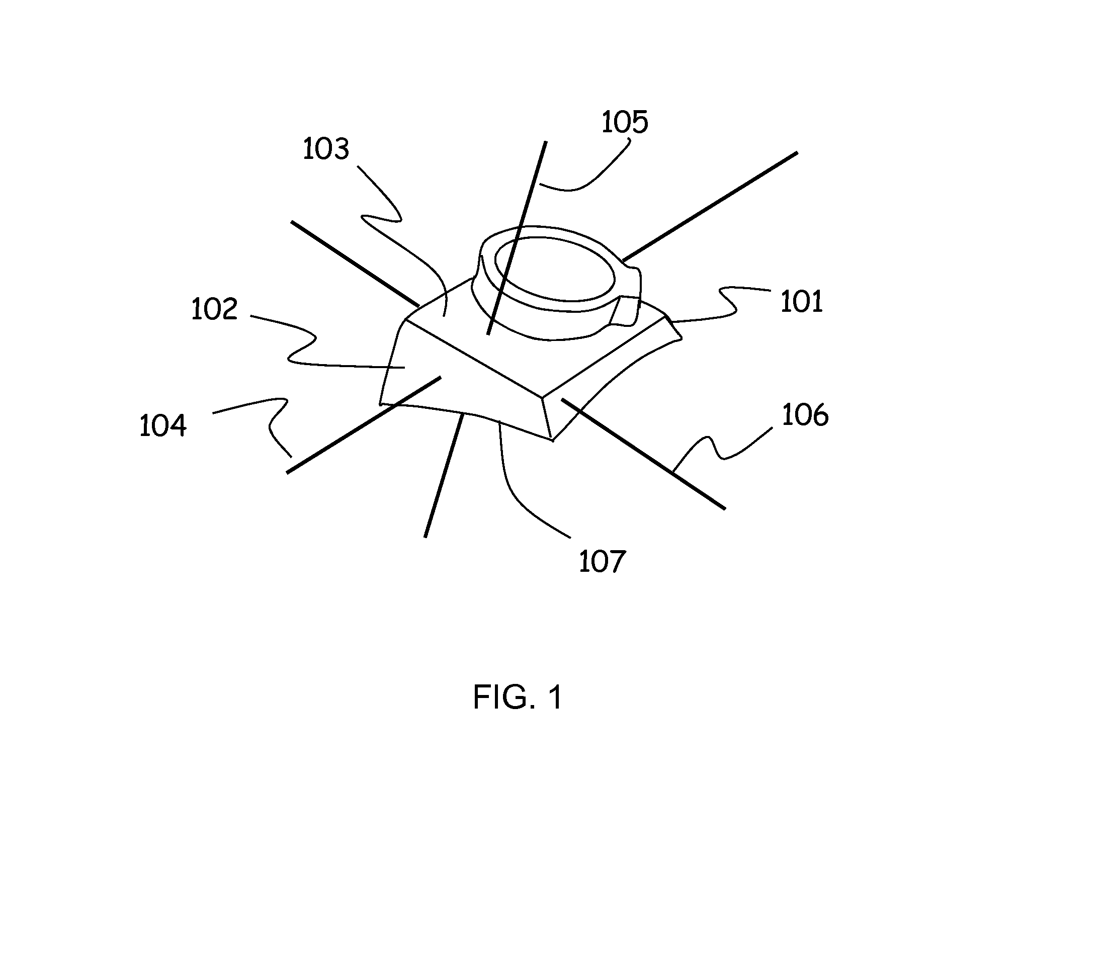
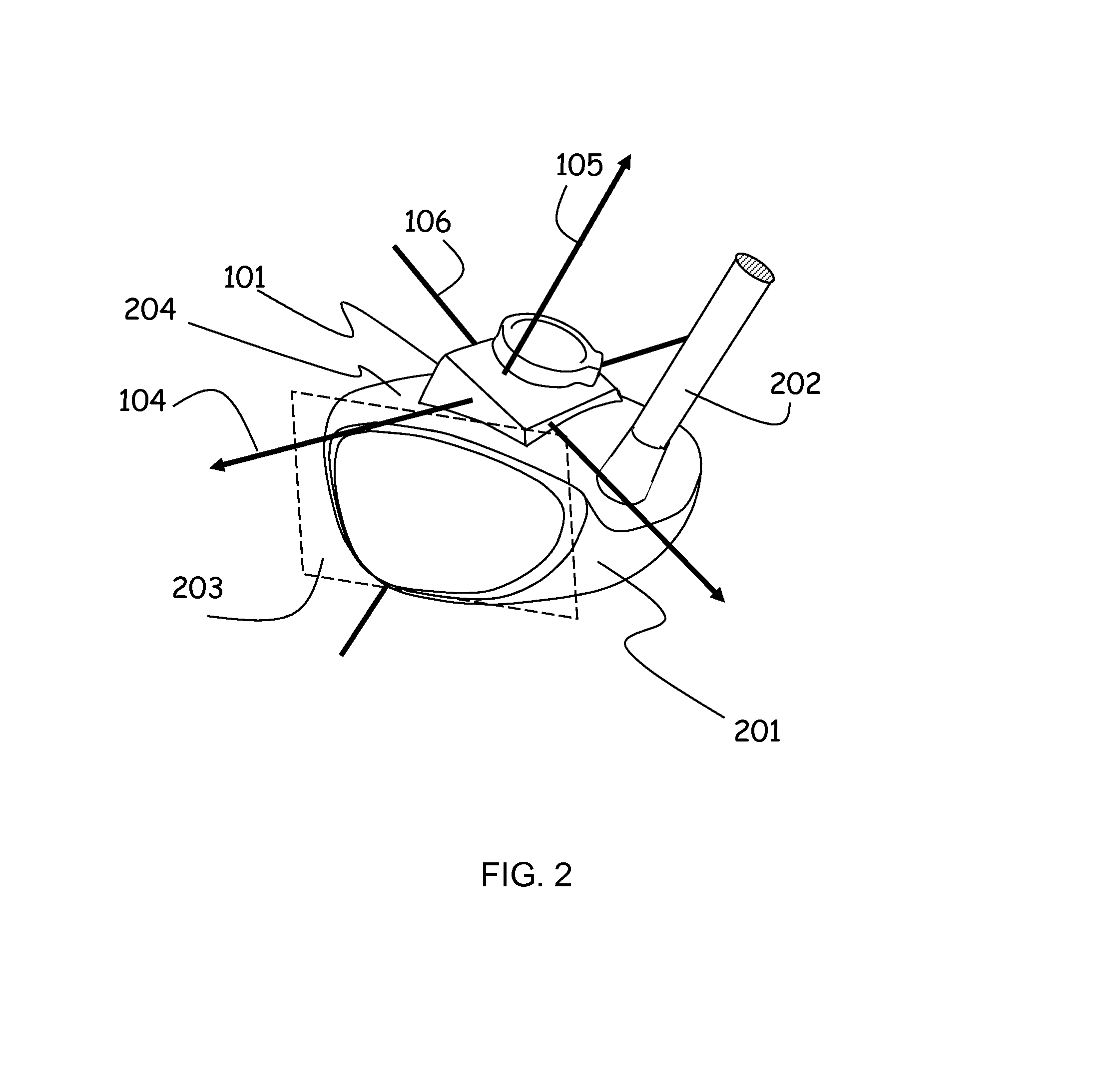
[0162]As shown in FIGS. 15 and 15A of the time-space correlation, the Club Head Module 101 (first module) comprises all existing electronics functions 1501, that include: a means of measurement of three orthogonal acceleration axes, implemented with a three axis accelerometer device or a combination of single or dual axis accelerometer devices to achieve acceleration measurement of three orthogonal axes, a means for an antenna that can be a PC embedded antenna or a chip component antenna, RF wireless communication functions providing a means for transmitting RF signals and a means of receiving RF signals implemented with common off the shelf RF integrated circuit device(s), circuit control and data processing and data formatting functions that provide a means for controlling all circuit functions, a means for data acquisition and a means for formatting data for various protocol structures all implemented with a common off the shelf integrated circuit device typically labeled MCU or ...

second embodiment

[0171]As shown in FIGS. 17 and 17A of the time-space correlation, the Club Head Module 101 (first module), comprises all existing electronics functions 1701, that include a means of measurement of three orthogonal acceleration axes, that can include but are not limited to the use of a three axis accelerometer device or a combination of single or dual axis accelerometer devices to achieve acceleration measurement of three orthogonal axes, a means for an antenna that can be a PCB embedded antenna or a chip component antenna, RF wireless communication functions providing a means for transmitting RF signals and a means of receiving RF signals implemented with common off the shelf RF integrated circuit device(s), circuit control and data processing and data formatting functions that provide a means for controlling all circuit functions, a means for data acquisition and a means for formatting data for various protocol structure all implemented with a common off the shelf integrated circui...

third embodiment

[0191]As shown in FIGS. 17 and 17A of the time-space correlation, the Club Head Module 101 (first module), comprises all existing electronics functions 1701, that include a means of measurement of three orthogonal acceleration axes, that can be implemented with but are not limited to the use of a three axis accelerometer device or any combination of single or dual axes accelerometer devices to achieve acceleration measurement of three orthogonal axes, a means for an antenna that can be implemented with a PCB embedded antenna or a chip component antenna, RF wireless communication functions providing a means for transmitting RF signals and a means of receiving RF signals implemented with common off the shelf RF integrated circuit device(s), circuit control and data processing and data formatting functions that provide a means for controlling all circuit functions, a means for data acquisition and a means for formatting data for various protocol structure all implemented with a common ...


PUM


Abstract

The presented invention relates to a method for determining the effectiveness of a golfer's swing without the requirement of the club head making contact with a golf ball. More specifically, the present invention relates to a measurement and analysis system comprising a first module that attaches to the club head and captures measurement receiver signal strength data during the entire swing time line and may capture motional data on same time line, further first module wirelessly communicates bi-directionally with a second module that is further connected to a user interface device and computational engine where feedback results are derived and conveyed to the golfer. The system provides comprehensive feedback for a swing characterization time line referenced to the spatial domain using receiver signal strength measurements that may be in combination with motional and dynamics orientation measurements.

Description

CROSS REFERENCE TO RELATED APPLICATION[0001]This patent application is a continuation-in-part application of patent application U.S. Ser. No. 13 / 290,124 filed on Nov. 6, 2011 entitled “Golf Free Swing Measurement and Analysis System” that is a continuation-in-part application of patent application U.S. Ser. No. 13 / 225,433 filed on Sep. 3, 2011 entitled “Golf Free Swing Measurement and Analysis System” that are both incorporated herein by reference.FIELD OF THE INVENTION[0002]The presented invention relates to a method for determining the effectiveness of a golfers swing without the requirement of the club head making contact with a golf ball. More specifically, the present invention relates to a system comprising a first module that attaches to the club head and captures measurement data and relative position data during the entire swing, further first module wirelessly communicates bi-directionally with a second module that is further connected to a user interface device and comput...

Claims


Application Information

Patent Timeline
Patent Type & Authority Applications(United States)
IPC IPC(8): A63B24/00A63B69/36
CPCA63B69/3632A63B24/0003A61B5/11A63B2220/40A63B2220/833A63B2225/20A63B2225/50G09B19/0038A63B24/0006A63B71/0619
Inventor DAVENPORT, ROGER
Owner GOLF IMPACT
Why Eureka
Try Eureka