
Electrical system for an aircraft

a technology for electric systems and aircraft, applied in the direction of electric/fluid circuits, circuit arrangements, vehicle components, etc., can solve the problems of large fuel consumption and typical increase in load size, and achieve the effect of increasing the generating efficiency of the system and the aircraft, and flexible connectivity

Active Publication Date: 2018-08-21
ROLLS ROYCE PLC
View PDF18 Cites 2 Cited by
  • Summary
  • Abstract
  • Description
  • Claims
  • Application Information

AI Technical Summary

Benefits of technology

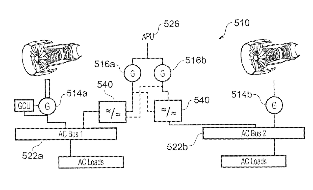
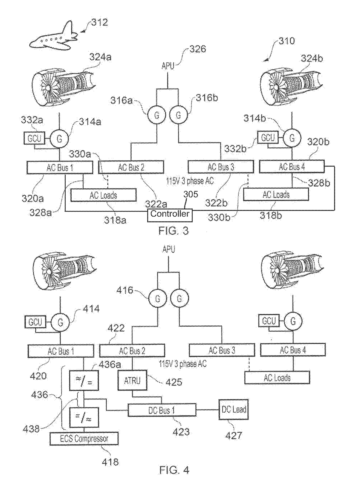
[0008]Providing the arrangement of the present invention allows more flexibility in the connectivity of the electrical power sources of the aircraft which can lead to an increase in the generating efficiency of system and aircraft as a whole.

Problems solved by technology

These loads typically increase in size with each new generation of civil aircraft to the point where the electrical loading on current aircraft and aircraft in development accounts for a significant portion of the fuel consumption.

Method used


Image

  • Electrical system for an aircraft
  • Electrical system for an aircraft
  • Electrical system for an aircraft

Examples


Embodiment Construction

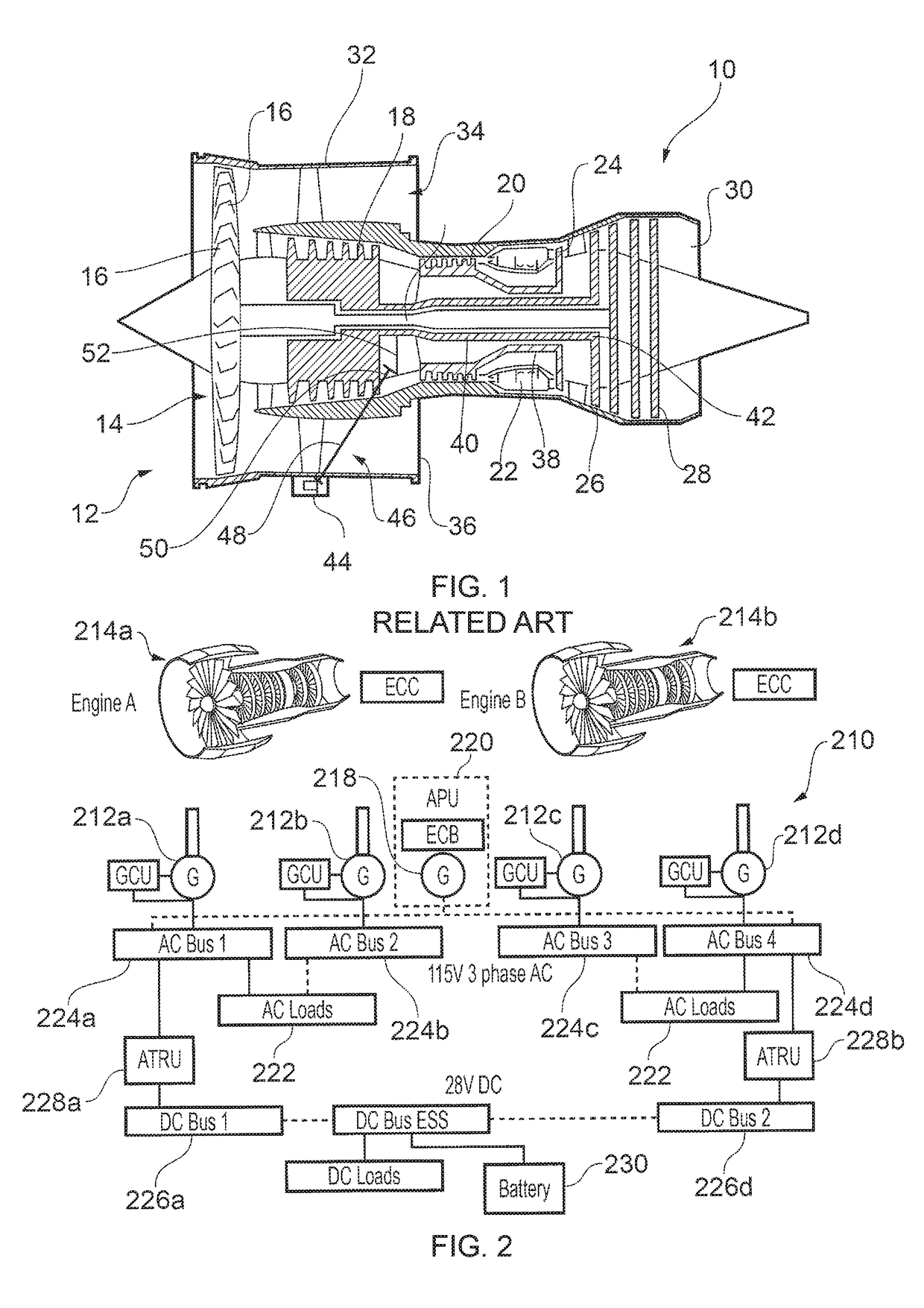
[0024]FIG. 2 shows a known electrical network 210 for an airframe. The electrical network 210 includes four electrical generators 212a-d, which are driven by prime movers in the form of power take-offs taken from gas turbine engines 214a, b. Each engine 214a, b drives two of the generators 212a-d, each from the same spool of the engine 214a, b in a similar configuration to that described in FIG. 1 for the single generator 44. Thus, each of the two generators 212a-d shown on the left hand side of FIG. 1 are connected to one of the high pressure or intermediate pressure spools of one engine, and the two generators on the right hand side to the corresponding spool of another engine 214a, b.

[0025]The arrangement includes a further generator 218 which is driven by a prime mover in the form of an auxiliary power unit, APU 220. The APU 220 is typically a small gas turbine but may be other forms of power source such as a reciprocating engine or fuel cell, for example. More than one other a...


PUM


Abstract

This invention relates to an electrical system for an aircraft, comprising: a first main generator connected to at least one load via a first bus; a second main generator connected to at least one load via a second bus; a first and a second auxiliary generator associated with the first and second buses, the auxiliary generators being driven by a common prime mover.

Description

TECHNICAL FIELD OF INVENTION[0001]This invention relates to an electrical system in the form of an electrical architecture or network for application in the aerospace industry. In particular, the invention relates to an electrical network for an aircraft having multiple electrical power sources which are electrically connected to provide power for a variety of loads.BACKGROUND OF INVENTION[0002]FIG. 1 shows a conventional ducted fan gas turbine engine 10 comprising, in axial flow series: an air intake 12, a propulsive fan 14 having a plurality of fan blades 16, an intermediate pressure compressor 18, a high-pressure compressor 20, a combustor 22, a high-pressure turbine 24, an intermediate pressure turbine 26, a low-pressure turbine 28 and a core exhaust nozzle 30. A nacelle 32 generally surrounds the engine 10 and defines the intake 12, a bypass duct 34 and a bypass exhaust nozzle 36.[0003]Air entering the intake 12 is accelerated by the fan 14 to produce a bypass flow and a core f...

Claims


Application Information

Patent Timeline
Patent Type & Authority Patents(United States)
IPC IPC(8): B64D47/00H02J3/46B60R16/03H02J4/00
CPCB60R16/03H02J4/00H02J3/46B64D2221/00H02J2310/44
Inventor VYAS, PARAG
Owner ROLLS ROYCE PLC
Learn More