Patch antenna with non-integrity bandgap structure

A patch antenna, a complete technology, applied in the antenna, radiation element structure, electrical components, etc., can solve the problems of insufficient low-elevation angle performance of the antenna, complicated production and analysis, unsatisfactory improvement effect of the antenna's low-elevation angle performance, etc. , to achieve the effect of improving the low elevation gain performance and improving the low elevation gain

Inactive Publication Date: 2011-08-24
BEIHANG UNIV
View PDF0 Cites 0 Cited by
  • Summary
  • Abstract
  • Description
  • Claims
  • Application Information

AI Technical Summary

Problems solved by technology

However, the effect of the traditional electromagnetic bandgap structure on improving the performance of the antenna at low elevation angles is not satisfactory.
At the same time, the traditional electromagnetic bandgap structure needs to be doped with other materials or perforated in the dielectric material (called substrate perforated type), and the production and analysis are relatively complicated (see: Zhu Fangming, Lin Qingchun. New electromagnetic (photonic) crystal paste Research Progress of Chip Antenna. Journal of Radio Science, April 2002, Volume 17, Issue 2)
Although in 1998, a new type of electromagnetic bandgap structure for microstrip lines was proposed (see: Yasushi Horri, Makoto Tsutsumi. Harmonic control by photonic band-gap on microstrip patch antenna. IEEE Microwave and Guided wave Letters, 1999, 9( 1); 13~15), it does not need to drill holes on the dielectric substrate, but only needs to etch a periodic structure (called high-impedance surface type) on the grounded metal plate to achieve the performance of photonic crystals, which greatly reduces the The difficulty of the work, but this kind of electromagnetic bandgap is far from enough to improve the performance of the antenna at low elevation angles

Method used


Image

  • Patch antenna with non-integrity bandgap structure
  • Patch antenna with non-integrity bandgap structure
  • Patch antenna with non-integrity bandgap structure

Examples


Embodiment Construction

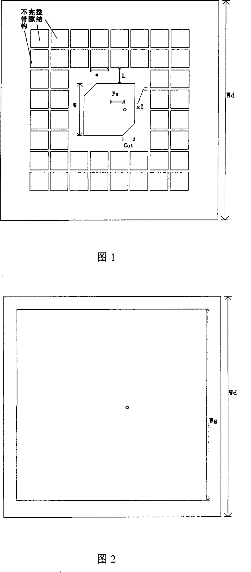
[0016] like figure 1 , 2, and 3, the structure of the present invention includes: the middle is a dielectric substrate, the outer layer is a metal skin on both sides, and one side is made of several small square patches without power feeding using the same method as the traditional radiation patch. It is a periodic unit, forming an incomplete n×n square block array. The so-called incomplete block array means that the central part of the n×n square block array does not place a periodic unit, and the vacant position is filled with a fed radiation patch replaced. n is usually greater than 1.

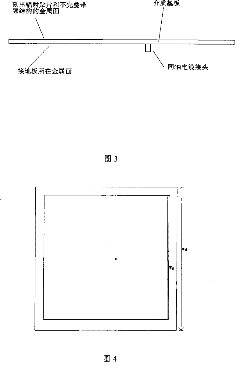
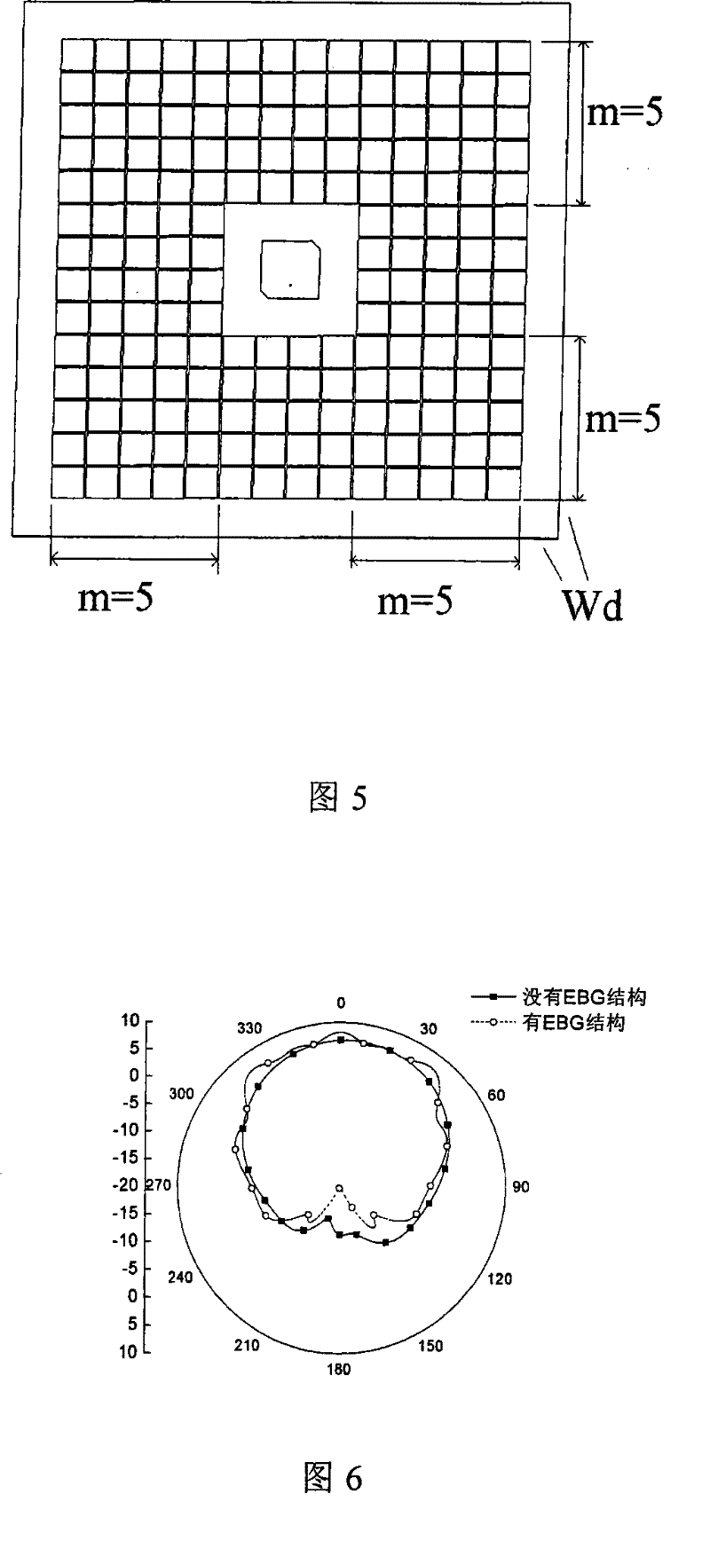
[0017] As shown in Figures 4, 5, and 6, at the same time, the present invention has more periodic structures, that is, the value of m is relatively large, such as when m≥5, a square ring of a certain width is removed from the edge of the metal ground plate of the patch antenna to form an infinite Complete floor structure. The general method of determining the value of m is: under the spe...


PUM


Abstract

The invention relates to an incomplete bandgap patch antenna. A plurality of small square patches called cycle unit without feeding are arranged on the metal surface of the antenna radiation patch, so as to form an incomplete nXn square matrix. The incompleteness of the matrix refers to the center of the nXn square matrix without the cycle unit. The vacant space is occupied by feeding radiation patches. The incomplete bandgap cycle units around the radiation patch are sufficient and simultaneously the edge of earthing board throws off a square loop with a certain breadth, which forms an incomplete earthing board structure. The invention had the advantage that the invention can effectively improve the low elevation angle gain property of traditional patch antenna.

Description

technical field [0001] The invention relates to a patch antenna, in particular to a patch antenna with an incomplete bandgap structure. Background technique [0002] Microstrip antennas are usually made of dielectric plates through photolithography or etching processes. The dielectric plate is usually composed of three parts: a thicker dielectric substrate (usually made of PTFE glass fiber or ceramic powder, etc.) in the middle, and a metal skin (usually copper) on both sides of the outer layer. A square (or rectangle, circle) is engraved on one side of the metal skin, and the rest of the metal part is removed (that is, the dielectric material is exposed), and the remaining square metal sheet is the radiation patch in the microstrip antenna, while the other side The metal skin is the ground plane of the microstrip antenna. A microstrip antenna designed with a complete square patch is usually a linearly polarized antenna, but if the surface of the radiating patch is slotted...

Claims


Application Information

Patent Timeline
Patent Type & Authority Patents(China)
IPC IPC(8): H01Q1/38H01Q13/08
Inventor 吕善伟赵晓纪
Owner BEIHANG UNIV
Why Eureka
Try Eureka