A Microstrip Antenna Using a Parasitic Feed Metal Post

A parasitic feeding, microstrip antenna technology, applied in the direction of antenna, antenna grounding device, antenna grounding switch structure connection, etc., can solve the problem of poor rotational symmetry of the radiation pattern, not meeting the hemispherical space coverage requirements, and inappropriate feeding position. Balance and other issues, to achieve the effect of improving rotational symmetry, improving circular polarization performance, and flexible position

Active Publication Date: 2016-06-01
XIAN INSTITUE OF SPACE RADIO TECH
View PDF8 Cites 0 Cited by
  • Summary
  • Abstract
  • Description
  • Claims
  • Application Information

AI Technical Summary

Problems solved by technology

The single-feed circularly polarized microstrip antenna has the most compact structure, but the circular polarization performance is poor; the design of the four-feed circularly polarized microstrip antenna needs to consider active reflection, and the feed network is more complex and the envelope size is larger , but the performance of circular polarization is the best; the design of dual-feed circularly polarized microstrip antenna is relatively simple, and the feeding network is not complicated (feeding through a power divider or bridge), and the performance of circular polarization is better than that of single-feed point antenna, but due to the unbalanced feed position, the rotational symmetry of the radiation pattern is still not good, and the gain at low elevation angles drops rapidly in some sections, which does not meet the hemispherical space coverage requirements

Method used


Image

  • A Microstrip Antenna Using a Parasitic Feed Metal Post
  • A Microstrip Antenna Using a Parasitic Feed Metal Post
  • A Microstrip Antenna Using a Parasitic Feed Metal Post

Examples


Embodiment Construction
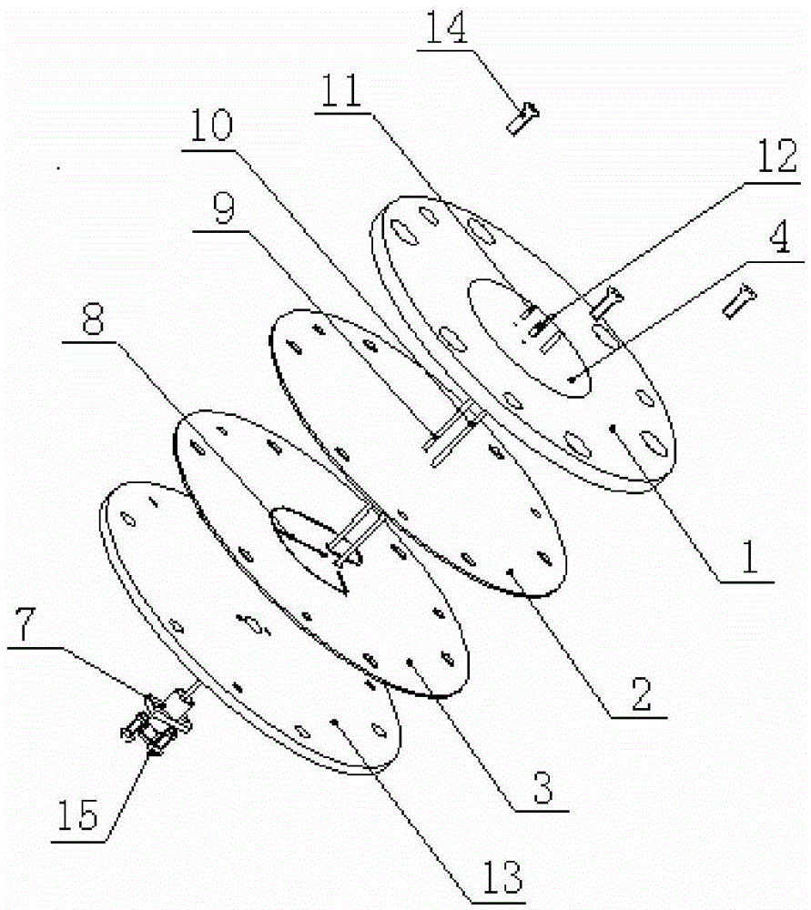
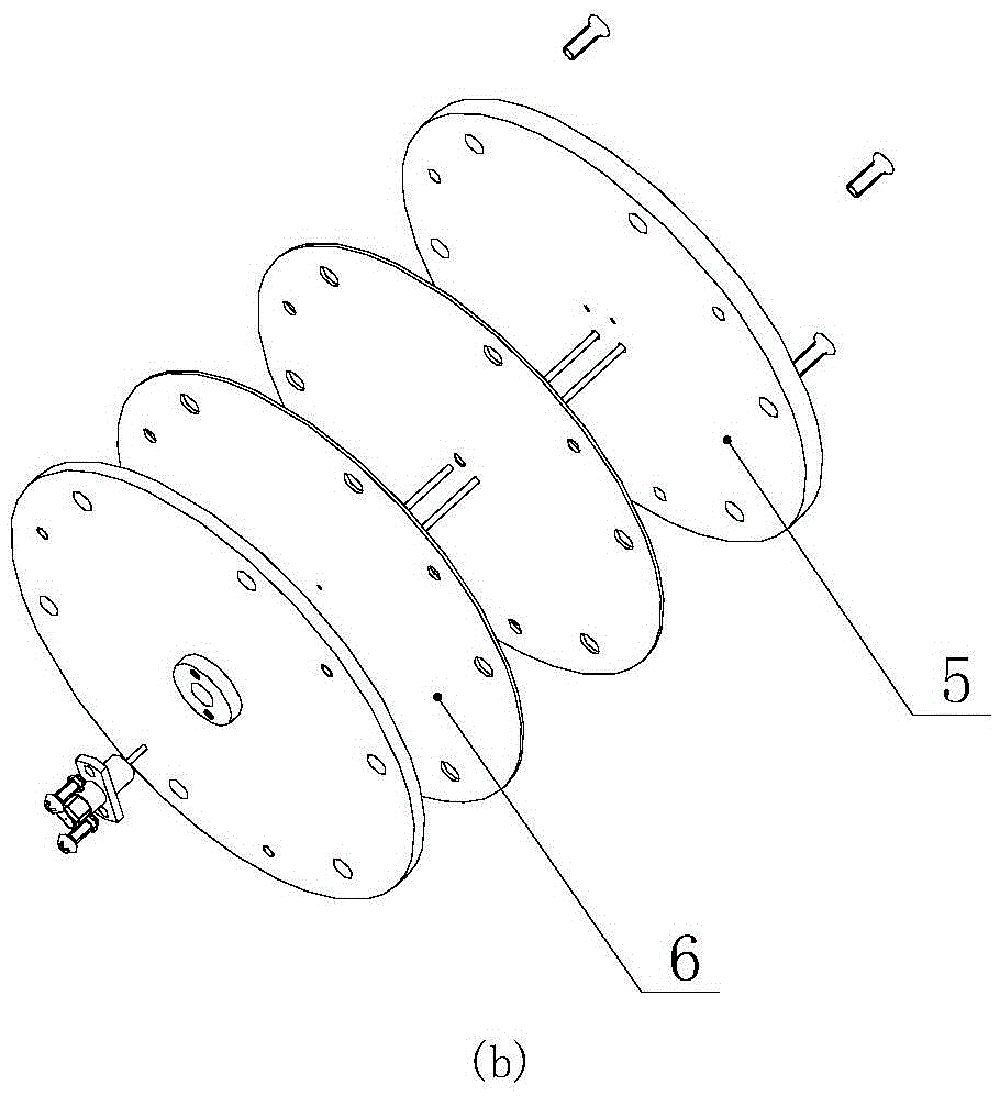
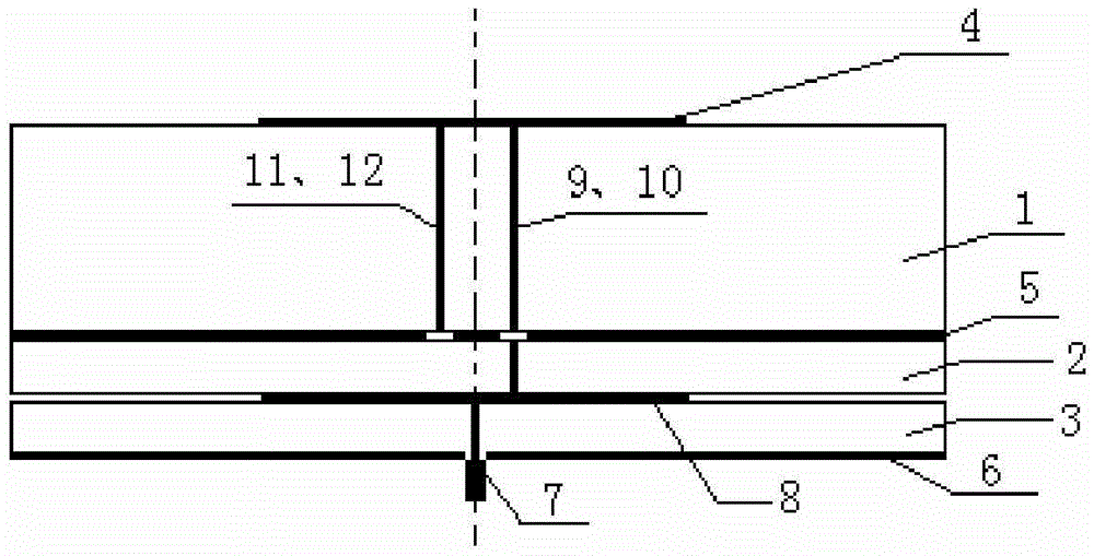
[0037]The basic idea of ​​the present invention: In order to develop a new circularly polarized microstrip antenna with simple structure, small envelope size, easy processing, manufacturing and assembly, and good rotational symmetry in the hemispherical space, this invention using parasitic feed metal Post microstrip antenna. On the basis of the double-feed point circularly polarized microstrip antenna, the present invention creatively applies the parasitic feed metal post, and obtains the radiation characteristics of a four-feed point microstrip antenna, which has a relatively rotationally symmetrical pattern and a high Low elevation gain, meeting the requirements of hemispherical space coverage, and the feed network is simple, easy to process and assemble. The parasitic feed metal post is not a short-circuit metal post, it is electrically isolated from the metal floor of the antenna, and is not electrically connected to the power divider, and only generates an induction fiel...


PUM


Abstract

A microstrip antenna using parasitical feed metal columns. The microstrip antenna includes four layers of dielectric plates, a radiating patch, metal floors, an SMP RF connector, a one-to-two power divider of a strip line form, a first feed metal column, a second feed metal column, a first parasitical feed metal column, and a second parasitical feed metal column. The antenna is additionally provided with the parasitical feed metal columns on the basis of a double-feed point circular polarization microstrip antenna, through electromagnetic coupling induction, the parasitical feed metal columns have electromagnetic field energy of a certain amplitude and phase, thereby changing surface current distribution of the microstrip antenna and electromagnetic field distribution between the microstrip antenna and the floors, so as to obtain a radiation pattern in rotational symmetry approximate to a ''four-feed point'' microstrip antenna, and at the same time, low elevation gain is improved, a feed network is simplified, feed loss is reduced, and the envelope size is diminished. The microstrip antenna using the parasitical feed metal columns in the invention is particularly suitable for occasions which have high requirements for miniaturization, rotational symmetry of a pattern and low elevation gain, and has popularization and application value.

Description

technical field [0001] The invention belongs to the technical field of antennas, and relates to a microstrip antenna using a parasitic feed post, and is particularly suitable for circularly polarized antennas with small envelope size, hemispherical space coverage, and high requirements for rotational symmetry of the radiation pattern. Background technique [0002] In the fields of satellite navigation, satellite positioning receiving system, aviation vehicle communication (low code rate), etc., it is often required to use circularly polarized antenna units with wider beams (for example, hemispherical space coverage), in order to improve low elevation gain or meet attitude changes Requirements, but also hope that the radiation pattern rotation symmetry is better. As platforms get smaller, the envelope size of such antennas needs to get smaller and smaller. [0003] At present, the commonly used spaceborne navigation antennas and spaceborne positioning receiving antennas are ...

Claims


Application Information

Patent Timeline
Patent Type & Authority Patents(China)
IPC IPC(8): H01Q1/50H01Q1/48H01Q1/38H01Q15/24
Inventor 贾秀娟彭鑫王景芳
Owner XIAN INSTITUE OF SPACE RADIO TECH
Why Eureka
Try Eureka