An electric transformer with improved cooling system

A technology of coil device and choke coil, which is applied in the direction of transformer/inductor coil/winding/connection, transformer/inductor parts, transformer/inductor magnetic core, etc., can solve the problem of cost and achieve low eddy current loss, Improved rotational symmetry and less noise

Inactive Publication Date: 2012-02-08
SIEMENS AG OESTERR
View PDF6 Cites 2 Cited by
  • Summary
  • Abstract
  • Description
  • Claims
  • Application Information

AI Technical Summary

Problems solved by technology

The shielding ring is a separate component and therefore entails additional costs during production

Method used


Image

  • An electric transformer with improved cooling system
  • An electric transformer with improved cooling system
  • An electric transformer with improved cooling system

Examples


Embodiment Construction

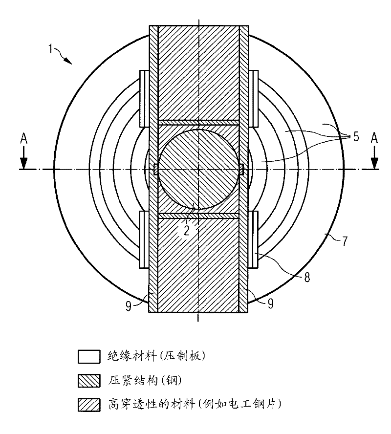
[0036] figure 1 The transformer 1 is shown in the region of a transformer leg 2 which carries a multipart coil 5 . The individual sections of the coil 5 are arranged concentrically around the leg axis 4 . A bearing and clamping device 8 formed of insulating material (press span) is pressed onto the pressure ring 7 . The bearing and clamping device 8 is supported on the yoke pressure plate 9 . Transformer leg 2 is composed of highly penetrating electrical steel sheets.

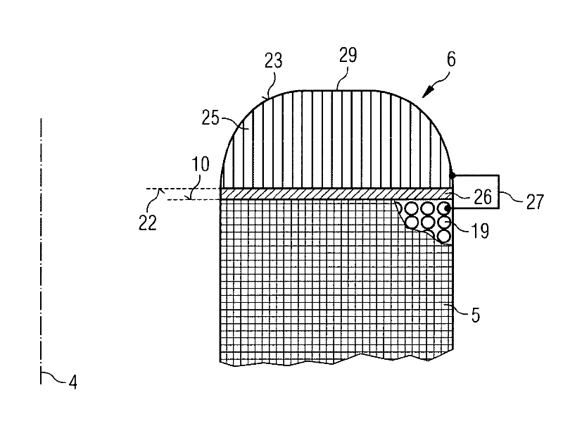
[0037] figure 2 The schematic diagram shows the basis of figure 1Sectional view of line A-A. The bearing and clamping device 8 presses the individual coils 5 in the axial direction (direction of the leg axis 4 ). In this case, coil covers 6 , which are respectively arranged on the end faces of the coil elements 5 , lie in the magnetic flux. As will be explained in more detail below in the exemplary embodiment, the coil cover 6 on the one hand brings about a deflection of the magnetic flux in the end reg...


PUM


Abstract

An electric transformer comprising: a magnetic core; at least one coil assembly which is positioned around a portion of the magnetic core and comprises a plurality of windings; a structure adapted for applying a clamping force on the magnetic core and / or the windings; and a cooling circuit adapted for conveying cooling fluid directly inside the coil assembly.

Description

technical field [0001] The invention relates to a coil arrangement for a transformer or a choke coil, the coil arrangement having an annular coil cover, which is arranged on the coil at the end side, wherein the side of the coil cover facing the coil is covered with the end face of the coil. Background technique [0002] In transformers or choke coils with high power ratings, the electrical coils are usually arranged concentrically around the legs of the soft magnetic core and are usually permanently clamped by means of a clamping structure. Part of the pressing arrangement is the so-called pressure ring or pressing ring, with which the axial pressing force is distributed as evenly as possible on the individual coils. The compression ring is usually arranged between the end face of the coil and the yoke arranged transversely to the leg. [0003] Such a compression ring for power transformers is known, for example, from US 3,750,070. The compression ring has a body which h...

Claims


Application Information

Patent Timeline
Patent Type & Authority Applications(China)
IPC IPC(8): H01F27/36
CPCH01F27/303H01F27/36H01F27/363H01F27/32H01F27/24H01F27/28
Inventor H.普雷加特纳M.斯卡拉
Owner SIEMENS AG OESTERR
Why Eureka
Try Eureka