
Slotting and milling process for vane of integral vane wheel

An integral impeller and processing method technology, applied in milling cutters, metal processing equipment, manufacturing tools, etc., can solve the problems of difficult interference between workpieces and tools, prolong cutting time, reduce processing efficiency, etc., and achieve easy guarantee of processing quality. The effect of improving machining efficiency and increasing cutting amount

Inactive Publication Date: 2007-06-27
WUHAN MARINE MACHINERY PLANT
View PDF0 Cites 32 Cited by
  • Summary
  • Abstract
  • Description
  • Claims
  • Application Information

AI Technical Summary

Problems solved by technology

[0003] 1. Since the cutting direction of the tool is basically parallel to the top surface of the blade, the blade is similar to the cantilever structure in the state of force, and the root of the blade bears a certain bending moment during processing, which is easy to deform and has poor rigidity; while the cutting force of the ball cutter during processing The radial component force is large, and the diameter of the ball cutter itself is small, the rigidity of the cutter bar is poor, the vibration is large during the processing, and the processing quality is difficult to control; moreover, due to the large radial component force, the blade and the tool give way to the knife. The deformation of the blades is difficult to control, making it difficult to guarantee the processing quality
[0004] 2. The length of the tool rod and the range of tool movement have great constraints on adjusting the interference between the workpiece and the tool
The diameter of the ball cutter is small, but its range of motion and the long diameter of the cutter bar are relatively large. In the process of adjusting the non-interference between the workpiece and the cutter, there are many restrictive factors, especially when the height of the blade is high. Tool interference is more difficult
[0005] 3. The tool path generated by ball cutter processing is long, and the rigidity of the tool is insufficient, so the feed rate and cutting amount cannot be increased, which prolongs the cutting time and reduces the processing efficiency

Method used


Image

  • Slotting and milling process for vane of integral vane wheel
  • Slotting and milling process for vane of integral vane wheel

Examples


Embodiment 1

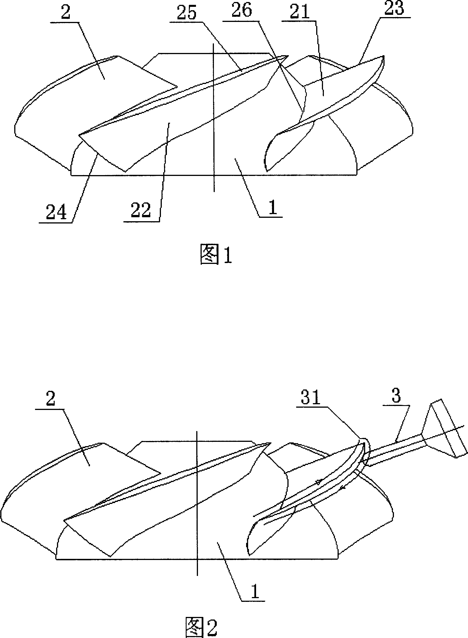
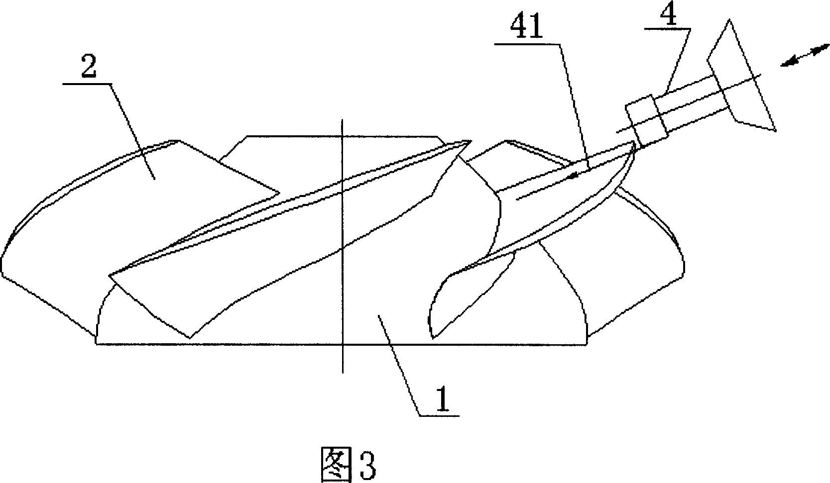
[0020] The free-form surface blade 2 of the axial-flow integral impeller is processed by the method of the present invention. The material of the impeller is ultra-low carbon duplex stainless steel, the maximum diameter of the impeller is 800-1000 mm, and the maximum height of the blade 2 is 240-260 mm. Processing is carried out on a five-coordinate CNC machining machine. The creation of the plunge milling cutter processing method and the generation of the program include the following steps:

[0021] 1 Establish the solid model of the impeller in the UG NX2.0 / CAD module.

[0022] 1.1 According to the design points given by the design drawings, connect the points of the same section with NURB splines (Non-Uniform Rational B-splines) to form a closed curve, and perform smoothing treatment.

[0023] The points given in the design drawings are the discrete points on the section of the blade 2. In order to generate the free-form surface of the blade 2, these points must be fitted...

Embodiment 2

[0047] Adopt ball cutter processing method and the inventive method to process and compare above-mentioned same integral impeller blade 2: adopt ball cutter processing earlier, the processing cycle of every integral impeller blade is about 17 days (20 hours every day), about 340 hours altogether; After adopting plunge milling cutter to process by the method of the present invention, the manufacturing cycle of every integral impeller blade is about 7 days, about 140 hours. The processing efficiency of the method of the invention is more than 2 times higher than that of the ball cutter processing, and the precision of the produced integral impeller product is greatly improved, and the quality is stably controlled, which fully meets the needs of large-diameter, high-precision impeller product processing.


PUM

PropertyMeasurementUnit
diameteraaaaaaaaaa
heightaaaaaaaaaa

Abstract

The slotting and milling cutter process for vane of integral vane wheel is completed in a numerically controlled machine tool with slotting and milling cutter advancing in the radial direction of the vane wheel and axial direction of the cutter. It has small radial force component caused by cutting, less vibration of the workpiece and the cutter, smooth cutting, small and controllable vane deformation, high machining quality and high machining efficiency. The present invention can meet the requirement of machining great diameter and high precision vane wheel product.

Description

technical field [0001] The invention relates to a cutting processing method for integral impeller blades, in particular to a plunge milling cutter processing method for integral impeller blades capable of processing the free-form surface blades of the integral impeller. Background technique [0002] The impeller is an indispensable key component in compressors, blowers, pumps and other machinery. When the impeller rotates, the blades do work on the fluid, changing the direction, speed or pressure of the fluid and realizing its mechanical function. According to the flow direction of the fluid, the impeller can be divided into two types: axial flow type and centrifugal type. The structure of the two impellers is composed of a hub and blades. The hub is a conical shell similar to a spherical segment. Blades are evenly distributed on the hub. There are two kinds of shapes: straight grain or free-form surface. The geometric shape of free-form surface blades has no certain rules a...

Claims


Application Information

Patent Timeline
Patent Type & Authority Applications(China)
IPC IPC(8): B23C5/18B23P15/02
Inventor 董洪林王益知汤敏吴红琼
Owner WUHAN MARINE MACHINERY PLANT
Learn More