Method for realizing machining of combustion-compression ring bushes by using combustion-compression ring bush cutting clamp

A processing method and ring sleeve technology, which is applied in the processing field of ring parts, can solve the problems of affecting the processing quality of the fuel pressure ring sleeve, poor precision of the fuel pressure ring sleeve, and easy deformation, so as to achieve clear and complete processing steps and ensure processing accuracy , the effect of preventing stress deformation

Active Publication Date: 2013-03-06
HARBIN TURBINE +1
View PDF5 Cites 27 Cited by
  • Summary
  • Abstract
  • Description
  • Claims
  • Application Information

AI Technical Summary

Problems solved by technology

[0003] The purpose of the present invention is to provide a processing method for the fuel pressure ring sleeve by using the fuel pressure ring sleeve cutting jig to solve the problem that the existing fuel pressure ring sleeve is easily deformed during processing because it is a thin-walled workpiece, thus affecting the fuel pressure ring. The processing quality of the ring sleeve, and the fuel pressure ring sleeve processed by the existing processing method has the problem of poor position accuracy of 30 equal parts of 30 holes

Method used


Image

  • Method for realizing machining of combustion-compression ring bushes by using combustion-compression ring bush cutting clamp
  • Method for realizing machining of combustion-compression ring bushes by using combustion-compression ring bush cutting clamp
  • Method for realizing machining of combustion-compression ring bushes by using combustion-compression ring bush cutting clamp

Examples


specific Embodiment approach 1

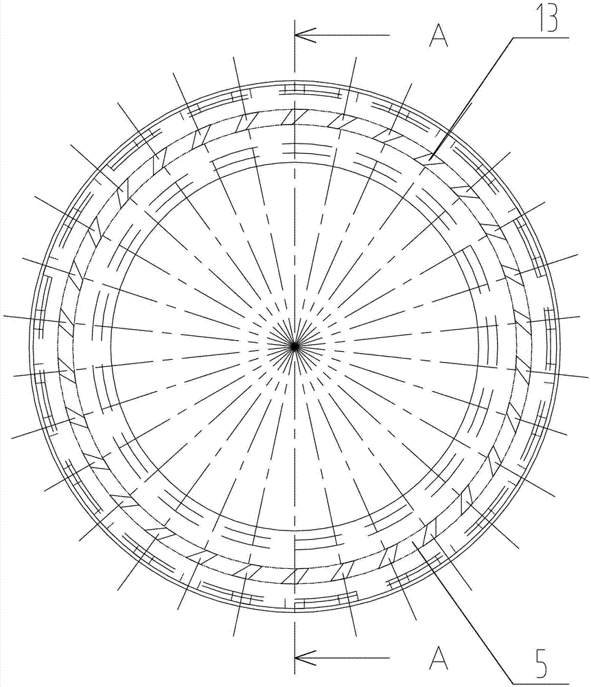
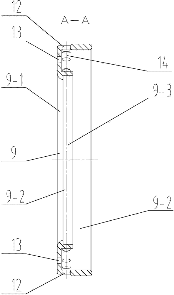
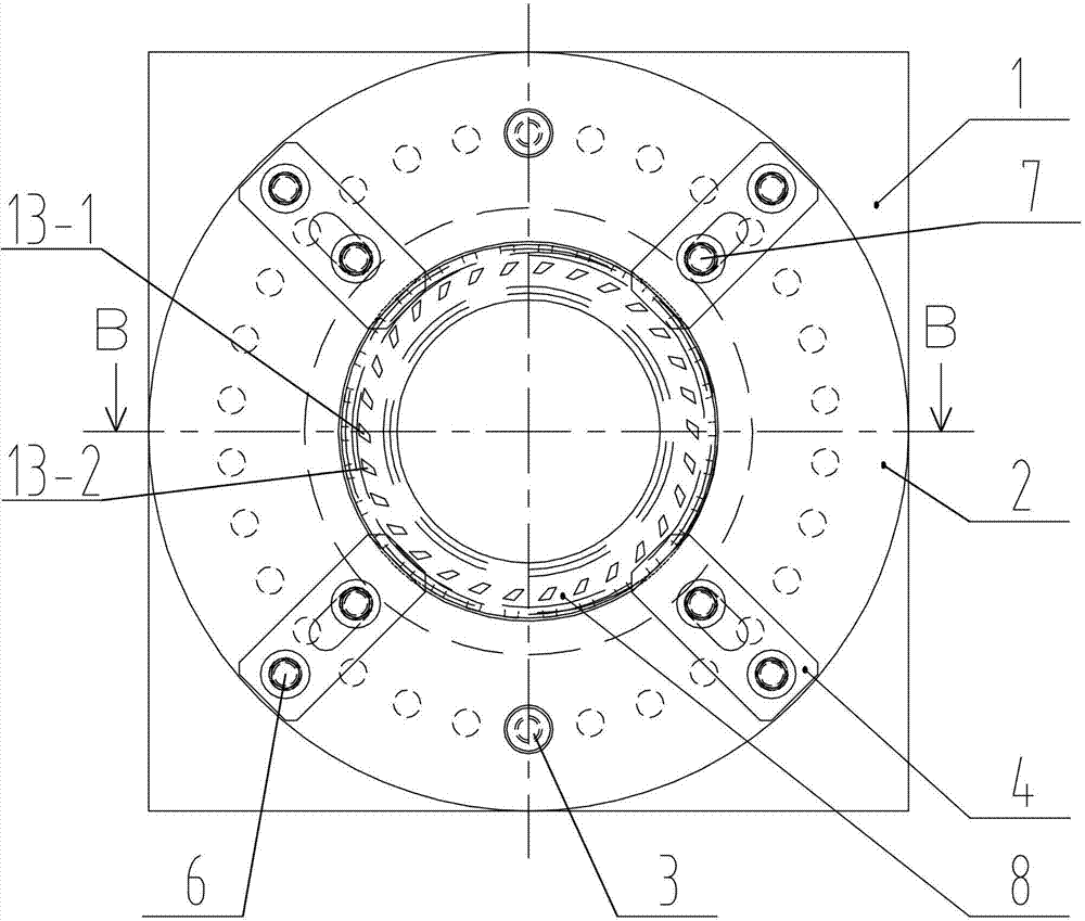
[0017] Specific implementation mode one: combine figure 1 , figure 2 , image 3 , Figure 4 , Figure 5 , Figure 6 , Figure 7 , Figure 8 , Figure 9 , Figure 10 , Figure 11 , Figure 12 , Figure 13 , Figure 14 and Figure 15 To illustrate this embodiment, the fuel pressure ring sleeve cutting jig used in the processing method of the fuel pressure ring sleeve in this embodiment includes a bottom plate 1, a turntable 2, two positioning pins 3 and four pressure plates 4, and the turntable 2 is located at Between the bottom plate 1 and the pressure plate 4, the center of the top surface of the turntable 2 is processed with a turntable counterbore 2-1, and the center of the bottom surface of the turntable 2 is processed with an outer boss 2-2, and the turntable counterbore 2-1 and the outer convex The table 2-2 is coaxially arranged, the aperture of the counterbore 2-1 of the turntable is 140mm, the shape of the outer boss 2-2 is cylindrical, and the outer diam...

specific Embodiment approach 2

[0028] Specific implementation mode two: combination image 3 , Figure 4 and Figure 5 Describe this embodiment, the fuel pressure ring sleeve cutting fixture in this embodiment also includes four support screws 6, the second threaded hole 4-1 is processed on the pressure plate 4, and the outer thread of the second threaded hole 4-1 The diameter is 12 mm, and the support screw 6 is detachably connected with the pressure plate 4 through the second threaded hole 4 - 1 on the pressure plate 4 . The setting of the supporting screw 6 can achieve a better supporting effect, which is more conducive to realizing the purpose of the present invention. Other method steps are the same as those in the first embodiment.

specific Embodiment approach 3

[0029] Specific implementation mode three: combination image 3 , Figure 4 and Figure 5 Describe this embodiment, the fuel pressure ring sleeve cutting fixture in this embodiment also includes four clamping screws 7, the pressure plate 4 is processed with a waist hole 4-2, and the clamping screws 7 pass through the pressure plate 4 in turn The upper waist hole 4-2 and the first threaded hole 2-4 of the turntable 2 detachably connect the pressing plate 4 to the turntable 2. The clamping screw 7 is set because in the specific processing process, the clamping force of the clamping screw 7 can be adjusted according to workpieces of different sizes, so that the clamping effect is better, and its operation is flexible and adjustable; the waist hole 4- 2 is R6.25 waist hole, R6.25 waist hole means that the fillet radius on both sides of the waist hole is 6.25mm. Other method steps are the same as those in the first or second embodiment.


PUM

PropertyMeasurementUnit
pore sizeaaaaaaaaaa

Abstract

The invention discloses a method for realizing the machining of combustion-compression ring bushes by using a combustion-compression ring bush cutting clamp, relating to a machining method for ring parts. The invention aims to solve the problems that because the existing combustion-compression ring bush is a thin-walled workpiece, the existing combustion-compression ring bush is easy to deform in the process of machining, so that the machining quality of the combustion-compression ring bush is affected, and meanwhile, the 30-equated positions of 30 molded holes of a combustion-compression ring bush machined by using the existing machining method are poor in accuracy. The clamp used in the invention comprises a base plate, a turntable, two positioning pins and four pressing plates. The method disclosed by the invention comprises the following steps of: 1, roughly turning an inner hole, an outer circumferential surface and two planes of a blank; 2, relieving stress of a semi-finished combustion-compression ring bush product; 3, carrying out finish turning on an inner hole, an outer circumferential surface and two planes of the semi-finished combustion-compression ring bush product; 4, drawing center position lines of radial holes and molded holes; 5, drilling 30 radial holes with a diameter of 5 mm; and 6, cutting and machining 30 molded holes. The method disclosed by the invention is used for machining combustion-compression ring bushes.

Description

technical field [0001] The invention relates to a processing method of an annular part, which belongs to the technical field of mechanical processing. Background technique [0002] The gas compressor unit is a mechanical device that converts the chemical energy of fossil fuels such as light diesel oil and natural gas into electrical energy. The ring sleeve is a component of the steam turbine combustion compressor unit, also known as the combustion pressure ring sleeve. The design requirements for the 30 holes of the combustion pressure ring sleeve during actual processing are that the contour of the hole is 0.05mm, and the position accuracy of each type of hole is 0.05mm. 0.08mm, this requirement makes the pressure ring easily deformed during processing because it is a thin-walled workpiece, which affects the processing quality of the pressure ring. At the same time, the pressure ring processed by the existing processing method has The problem of poor position accuracy of 3...

Claims


Application Information

Patent Timeline
Patent Type & Authority Applications(China)
IPC IPC(8): B23Q3/00B23P15/00
Inventor 孙盛丽赵祎昕魏崇巍魏成双
Owner HARBIN TURBINE
Why Eureka
Try Eureka