Bed for medical imaging apparatus

A photographic device and medical image technology, which is applied in the field of beds for medical image photographic devices, can solve the problems of increased weight, unfreedom of limbs, inconvenient loading of test objects, etc., and achieve the effect of light weight and less deformation

Active Publication Date: 2012-04-11
HITACHI HEALTHCARE MFG LTD
View PDF5 Cites 29 Cited by
  • Summary
  • Abstract
  • Description
  • Claims
  • Application Information

AI Technical Summary

Problems solved by technology

[0008] However, in the above-mentioned Patent Document 1, since the center base for lateral movement and the lower frame are provided on the elevating movement mechanism, and the upper frame for vertical movement is stacked thereon, the multilayer structure, therefore, The weight increases due to the addition of parts other than the frame, or the height of the bed at the lowest position becomes higher than that of a device without a multi-layer structure, so it may be inconvenient to place a test subject whose limbs are not free on the top plate on the situation
Furthermore, there are many movable parts and intermediate support members, and there is a problem that the displacement of the top plate part increases due to the accumulation of deformation of each part.

Method used


Image

  • Bed for medical imaging apparatus
  • Bed for medical imaging apparatus
  • Bed for medical imaging apparatus

Examples


no. 1 approach 》

[0032] The first embodiment is an embodiment in which a medical imaging device bed (hereinafter referred to as "bed") of the present invention is applied to an X-ray CT apparatus. A zoom arm is used as an elevating device for the bed, and the structural parts of the zoom arm are It is shared as a vertical moving device and a horizontal moving device.

[0033] (the whole frame)

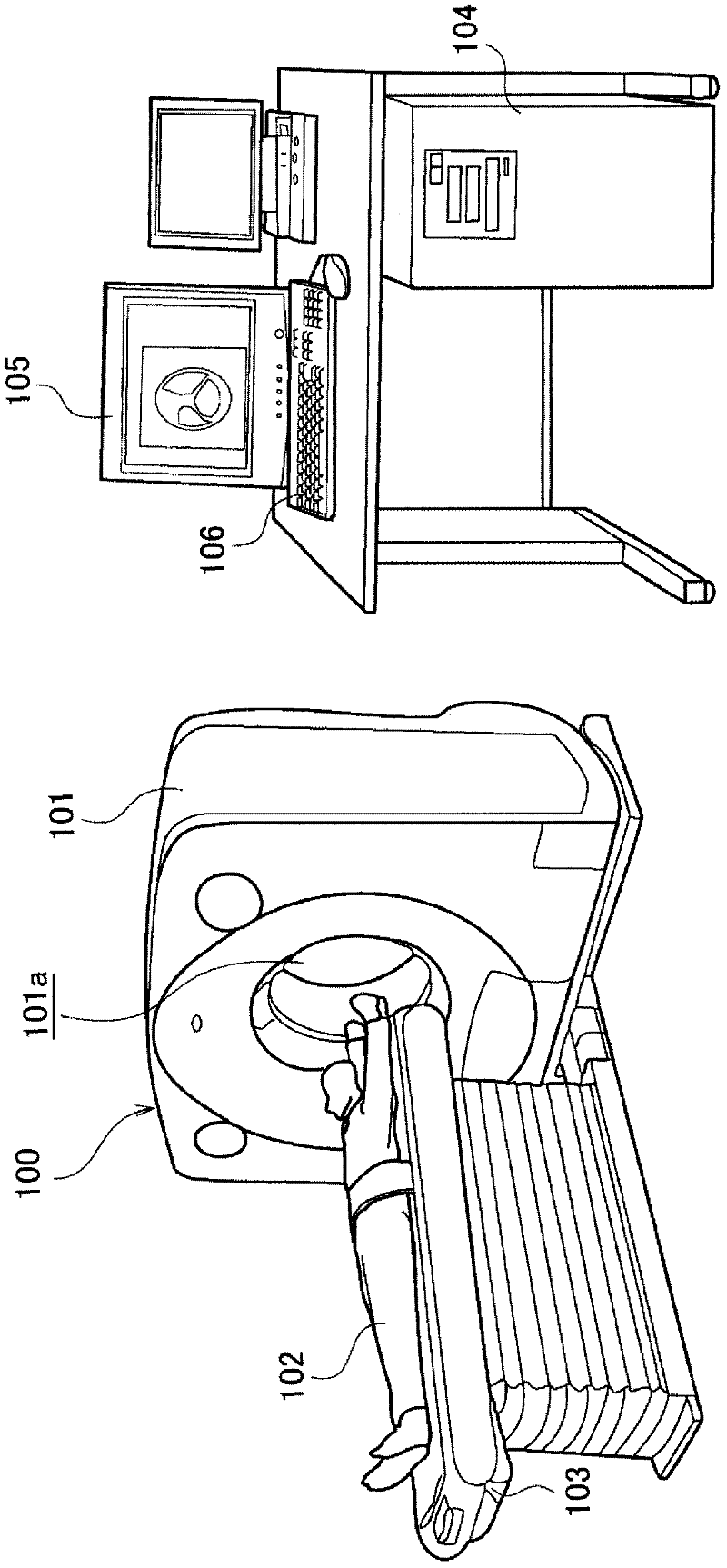
[0034] according to figure 1 The overall configuration of the X-ray CT apparatus 1 will be described. figure 1 It is the overall structure diagram of the X-ray CT apparatus. figure 1 The X-ray CT apparatus 100 has: a gantry 101, which is equipped with an X-ray tube device and an X-ray detector and rotates around the object 102, detects X-rays passing through the object 102 and sends transmitted X-ray signals; Bed 103, which mounts the subject 102 on the top plate and transports the subject 102 to the opening 101a of the gantry 101; a control device 104, which controls the X-ray CT apparatus 100 acco...

no. 2 approach 》

[0062] The second embodiment relates to a lateral movement device of an alternative example to the lateral movement device of the first embodiment. based on the following Figure 10 , Figure 11 A lateral movement device according to the second embodiment will be described. Figure 10 It is a side view of the lateral movement device related to the second embodiment, Figure 11 is along Figure 10 A cross-sectional enlarged view of B-B'.

[0063] In the lateral movement device of the second embodiment, the ball screw 24 is used as the rotating shaft 18 to move the upper frame 2 laterally as both a slide shaft and a drive shaft. More specifically, each guide rail support block 17 has a through hole 17h for passing the rotating shaft 18 to support the rotating shaft 18, and has a screw groove (not shown) screwed with the ball screw 24 on its inner peripheral surface. Show).

[0064] On the other hand, the motor 10 is fixed near the upper end of the outer arm 5 by the motor ...

no. 3 approach 》

[0066] Below, according to Figure 12 A lateral movement device according to a third embodiment will be described. Figure 12It is a partially enlarged view showing a side view of the lateral movement device according to the third embodiment. The lateral movement device according to the third embodiment is a lateral movement device that connects the rotation shaft 18 of the pantograph arm 40 and the rail support block 17 provided on the lower surface of the upper frame 2 via the lateral guide rail 28 . In this lateral movement device, the rotary shaft 18 constituting the elevating device and the guide rail support block 17 constituting the elevating device and the longitudinal movement device are shared as components of the lateral movement device. In the first and second embodiments, the guide rail support block functions as a rotation bearing, but in the third embodiment, the guide rail support block does not function as a rotation bearing, and the outer frame 5 rotates rel...


PUM


Abstract

Provided is a bed for a medical imaging apparatus equipped with a lightweight lateral motion device in which the deformation amount is reduced while limiting the height of the bed at the bottom of a top board. The bed for the medical imaging apparatus comprises a base (8), an upper frame (2) which supports a top board (1), and a lifting and lowering device (40) located between the base (8) and the upper frame (2) and lifting and lowering the upper frame (2), wherein the lifting and lowering device (40) is equipped with a lateral motion device (a motor (10), a pinion gear (12), a rack (23)) which moves at least two members (a rail receiving block (17) and a rotating shaft (18), and a rail receiving block (15) and a rotating shaft (20)) constituting the lifting and lowering device (40) relatively along the direction perpendicular to the longitudinal direction of the upper frame (2) in the top board plane of the top board.

Description

technical field [0001] The present invention relates to a bed for a medical imaging device, and more particularly, to a bed for a medical imaging device that can facilitate adjustment of an imaging field of view of a subject placed on a top plate. Background technique [0002] When performing CT imaging with an X-ray CT apparatus, since the imaging is performed centering on the body axis of the subject, in order to image organs such as the heart that deviate from the center of the body axis, a wide range of imaging is required. As a result, resulting in increased exposure to radiation. Therefore, as one of the methods of reducing the dose of radiation in areas other than the imaging target, the bed for X-ray CT apparatus is adopted, that is, the bed for X-ray CT apparatus has a lateral movement device that moves the top plate toward the body. The axial direction is moved in a direction perpendicular to the axis so that an imaging subject at a position deviated from the body...

Claims


Application Information

Patent Timeline
Patent Type & Authority Applications(China)
IPC IPC(8): A61B6/04
CPCA61B6/0457A61B6/0407A61B6/03A61B6/0487
Inventor 宫野岩坂中健也
Owner HITACHI HEALTHCARE MFG LTD
Why Eureka
Try Eureka