Dual-frequency wide-beam microstrip antenna working in S wave band

A microstrip antenna and band technology, applied in the field of communication, can solve the problems of insufficient low-elevation-angle gain and narrow space-borne antenna beam, and achieve the effect of reducing volume and weight, improving low-elevation-angle gain, and ensuring radiation.

Pending Publication Date: 2021-05-07
NO 8511 RES INST OF CASIC
View PDF1 Cites 0 Cited by
  • Summary
  • Abstract
  • Description
  • Claims
  • Application Information

AI Technical Summary

Problems solved by technology

[0004] The purpose of the present invention is to provide a dual-band width beam microstrip antenna working in the S-band, which solves the problems of narrow beams and insufficient gain at low elevation angles of space-borne antennas, and effectively realizes the miniaturization of the antenna

Method used


Image

  • Dual-frequency wide-beam microstrip antenna working in S wave band
  • Dual-frequency wide-beam microstrip antenna working in S wave band
  • Dual-frequency wide-beam microstrip antenna working in S wave band

Examples


Embodiment 1

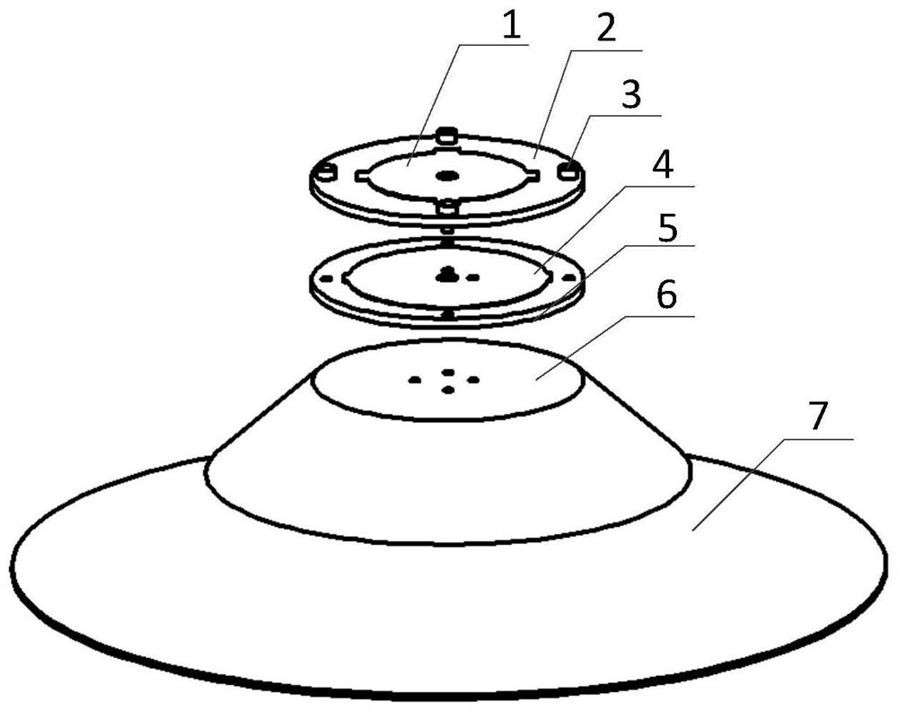
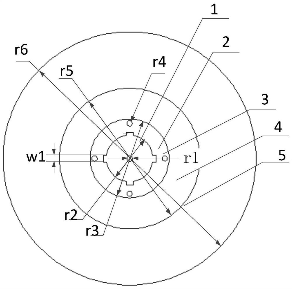
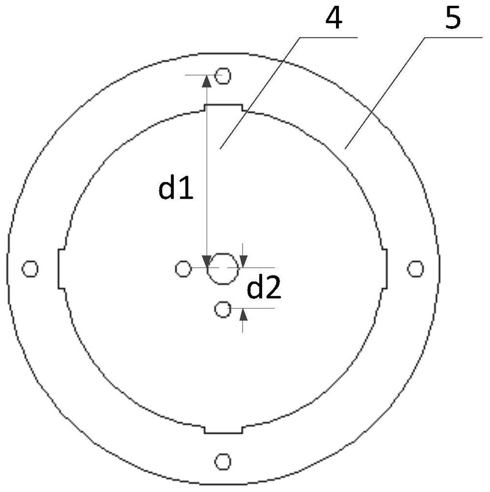
[0026] combine figure 1 , the upper radiation patch 1 is located on the upper dielectric substrate 2, the lower radiation patch 4 is located on the lower dielectric substrate 5, the bottom surface of the upper dielectric substrate 2 is connected to the top surface of the lower dielectric substrate 5, and both dielectric substrates are F4BTM-1 / 2 plate, the thickness is 2mm, the loss tangent is 0.0015, the dielectric constant of the upper plate is 3.5, and the dielectric constant of the lower plate is 2.6. Both microstrips are fed by coaxial probes. The coaxial probes of the lower microstrip antenna pass through the lower dielectric substrate 5 and are connected to the lower metal radiation patch 4. The two feeding points are at a 90° angle to the center of the radiation patch. ° angle, the coaxial probe of the upper microstrip antenna passes through the upper dielectric substrate 2 and connects with the upper metal radiation patch 1, the two coaxial probes also form an angle o...


PUM

PropertyMeasurementUnit
radiusaaaaaaaaaa
thicknessaaaaaaaaaa
heightaaaaaaaaaa

Abstract

The invention discloses a dual-frequency wide-beam microstrip antenna working in an S wave band. The dual-frequency wide-beam microstrip antenna comprises an upper-layer metal radiation patch, an upper-layer dielectric substrate, a metal screw, a lower-layer metal radiation patch, a lower-layer dielectric substrate, a metal boss and a metal reflecting plate, wherein the upper-layer dielectric substrate, the lower-layer dielectric substrate, the metal boss and the metal reflecting plate are sequentially arranged from top to bottom, the metal boss is in a bowl shape, the plane of the bottom of the bowl is fixed to the center of the top surface of the metal reflecting plate in an upside-down mode upwards, reverse current appears in the front top direction of the antenna by changing the length of an emission path of electromagnetic waves, the directional diagram of antenna is enabled to be saddle-shaped consequently, the upper-layer metal radiation patch is adhered to the center of the top surface of the upper-layer dielectric substrate, the lower-layer metal radiation patch is adhered to the center of the top surface of the lower-layer dielectric substrate, and the upper-layer dielectric substrate and the lower-layer dielectric substrate are fixed on the top surface of the metal boss through a plurality of metal screws. According to the invention, the problems of narrow beam and insufficient low-elevation gain of a satellite-borne antenna are solved, and the miniaturization of the antenna is effectively realized.

Description

technical field [0001] The invention belongs to the communication technology, in particular to a microstrip antenna with double-band width beams working in the S band. Background technique [0002] At present, with the development of communication technology and the improvement of satellite launch technology, satellites have received more and more attention in the fields of navigation and positioning, remote sensing and telemetry. In satellite communication, in order to ensure communication within a certain angle, the antenna is generally required to have a wide The characteristics of the beam, and ensure that the antenna has a certain gain at low elevation angles; due to the limited volume of the system, the antenna must also be miniaturized, and the transmitting and receiving antennas must be integrated. [0003] In order to realize the wide-beam characteristics of the antenna, dipole antennas are often used in communication. For example, CN110890619A discloses a dipole an...

Claims


Application Information

Patent Timeline
Patent Type & Authority Applications(China)
IPC IPC(8): H01Q1/38H01Q1/50H01Q1/52H01Q5/10H01Q5/307H01Q15/14
CPCH01Q1/38H01Q1/50H01Q1/525H01Q15/14H01Q5/10H01Q5/307
Inventor 张一培苏抗樊书辰高晓堃江锋孙旭林新平
Owner NO 8511 RES INST OF CASIC
Why Eureka
Try Eureka