Load resistant microstrip antenna

A technology of a microstrip antenna and a dielectric material layer, which is applied in directions such as antennas and radiating element structures suitable for movable objects, can solve the problem of unsatisfactory lateral gain and lateral back gain, affecting the communication between the missile body and the satellite in the sky. , affecting the missile hit the target and other issues

Inactive Publication Date: 2015-08-26
HARXON CORP
View PDF23 Cites 0 Cited by
  • Summary
  • Abstract
  • Description
  • Claims
  • Application Information

AI Technical Summary

Problems solved by technology

The dielectric substrate of the traditional microstrip antenna is integrally processed from the same dielectric material, and its side gain and side back gain are usually not ideal
During the descent of the projectile, if the gain of the lat...

Method used


Image

  • Load resistant microstrip antenna
  • Load resistant microstrip antenna
  • Load resistant microstrip antenna

Examples


Embodiment Construction

[0021] In order to make the above objects, features and advantages of the present invention more comprehensible, specific implementations of the present invention will be described in detail below in conjunction with the accompanying drawings. In the following description, numerous specific details are set forth in order to provide a thorough understanding of the present invention. However, the present invention can be implemented in many other ways different from those described here, and those skilled in the art can make similar improvements without departing from the connotation of the present invention, so the present invention is not limited by the specific implementations disclosed below.

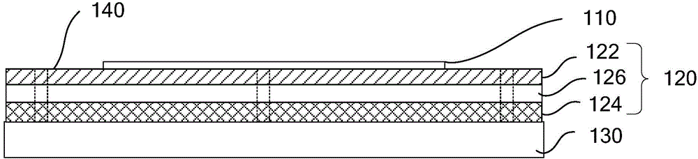
[0022] Please refer to figure 1 , is a layered structure diagram of the antiload microstrip antenna in an embodiment.

[0023] The antiload microstrip antenna includes a radiation sheet 110, a dielectric layer 120 and a ground layer 130 ( figure 2 not shown), the dielectric layer 1...


PUM


Abstract

The invention relates to a load resistant microstrip antenna, comprising a radiation piece, a dielectric layer and a grounding layer which are stacked in sequence, wherein the dielectric layer comprises more than two dielectric material layers which are different in dielectric constant; and the dielectric layer comprises a first dielectric material layer contacted with the radiation piece and a second dielectric material layer contacted with the grounding layer, and the dielectric constant of the second dielectric material layer is greater than the dielectric constant of the first dielectric material layer. The load resistant microstrip antenna can improve the low-elevation gain.

Description

technical field [0001] The invention relates to the technical field of antennas, in particular to an anti-load microstrip antenna. Background technique [0002] During the flight, the attitude of the projectile will change. When it is launched, it is launched obliquely upward at a certain angle. After a period of time, there will be a process of level flight, and finally it will fly downward to the target at a certain angle. The entire trajectory Approximate to a parabola. The anti-load antenna is generally installed at the front end of the projectile. When the projectile rises, the anti-load antenna is obliquely upward, and it uses the forward and front side directions to receive communications from the satellites above. After that, the projectile will enter the attitude of horizontal flight, and the anti-load antenna is used to receive the navigation signal from the satellite in the sky sideways. Finally, the missile will fly obliquely downward, and the anti-load antenna...

Claims


Application Information

Patent Timeline
IPC IPC(8): H01Q1/38H01Q1/28
Inventor 王春华邱诗贵
Owner HARXON CORP
Why Eureka
Try Eureka