Molding metal mold and method for manufacturing molding product

A technology for forming metal and metal molds, which is applied to home appliances, other home appliances, optical components, etc., can solve problems such as positioning errors, and achieve the effect of accurately determining the axial position

Inactive Publication Date: 2008-05-28
FUJIFILM CORP
View PDF1 Cites 4 Cited by
  • Summary
  • Abstract
  • Description
  • Claims
  • Application Information

AI Technical Summary

Problems solved by technology

However, gaps can cause problems with positioning errors

Method used


Image

  • Molding metal mold and method for manufacturing molding product
  • Molding metal mold and method for manufacturing molding product
  • Molding metal mold and method for manufacturing molding product

Examples


no. 1 example

[0037] Referring to the accompanying drawings, embodiments of the present invention will be described in detail below.

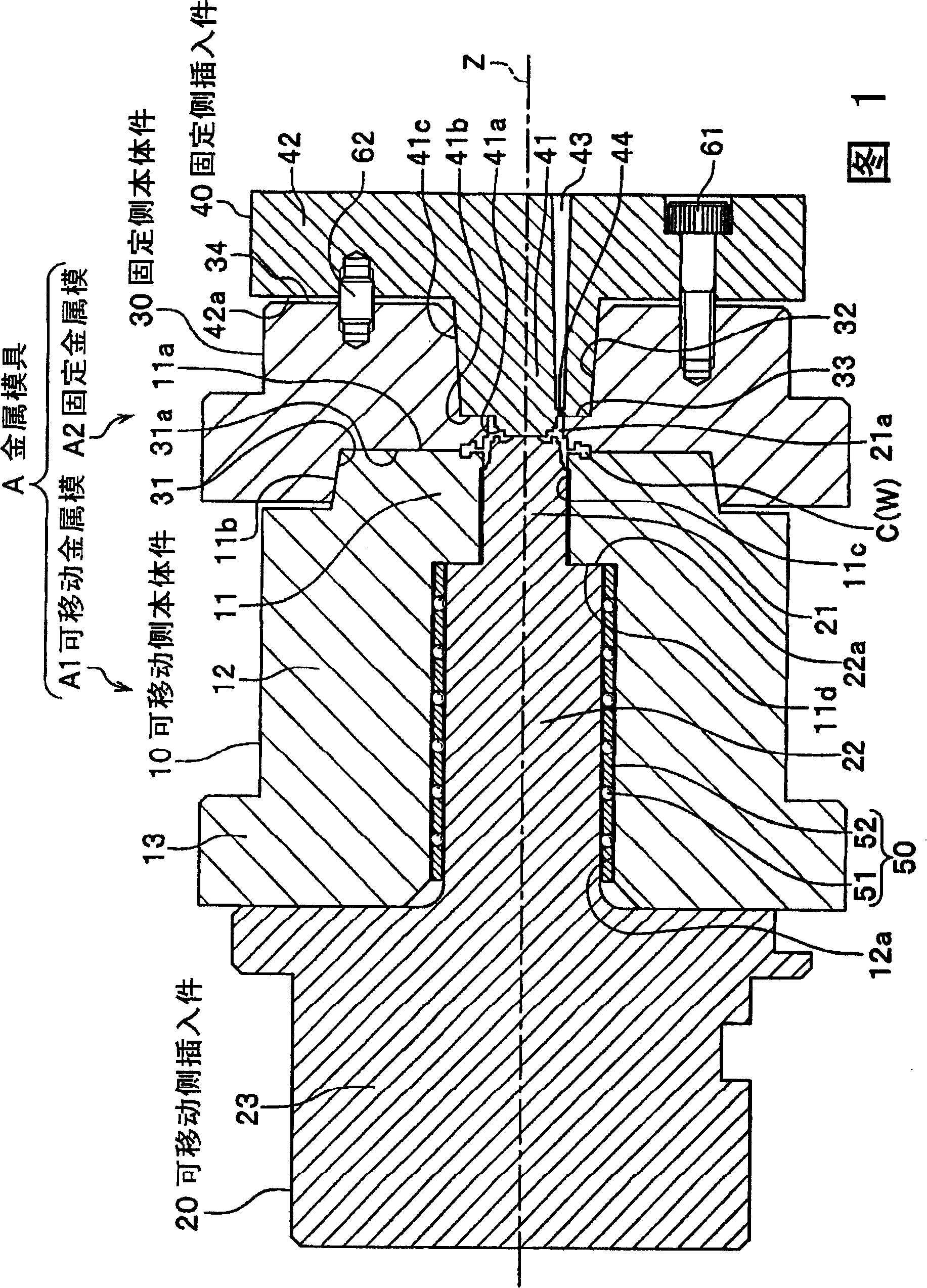
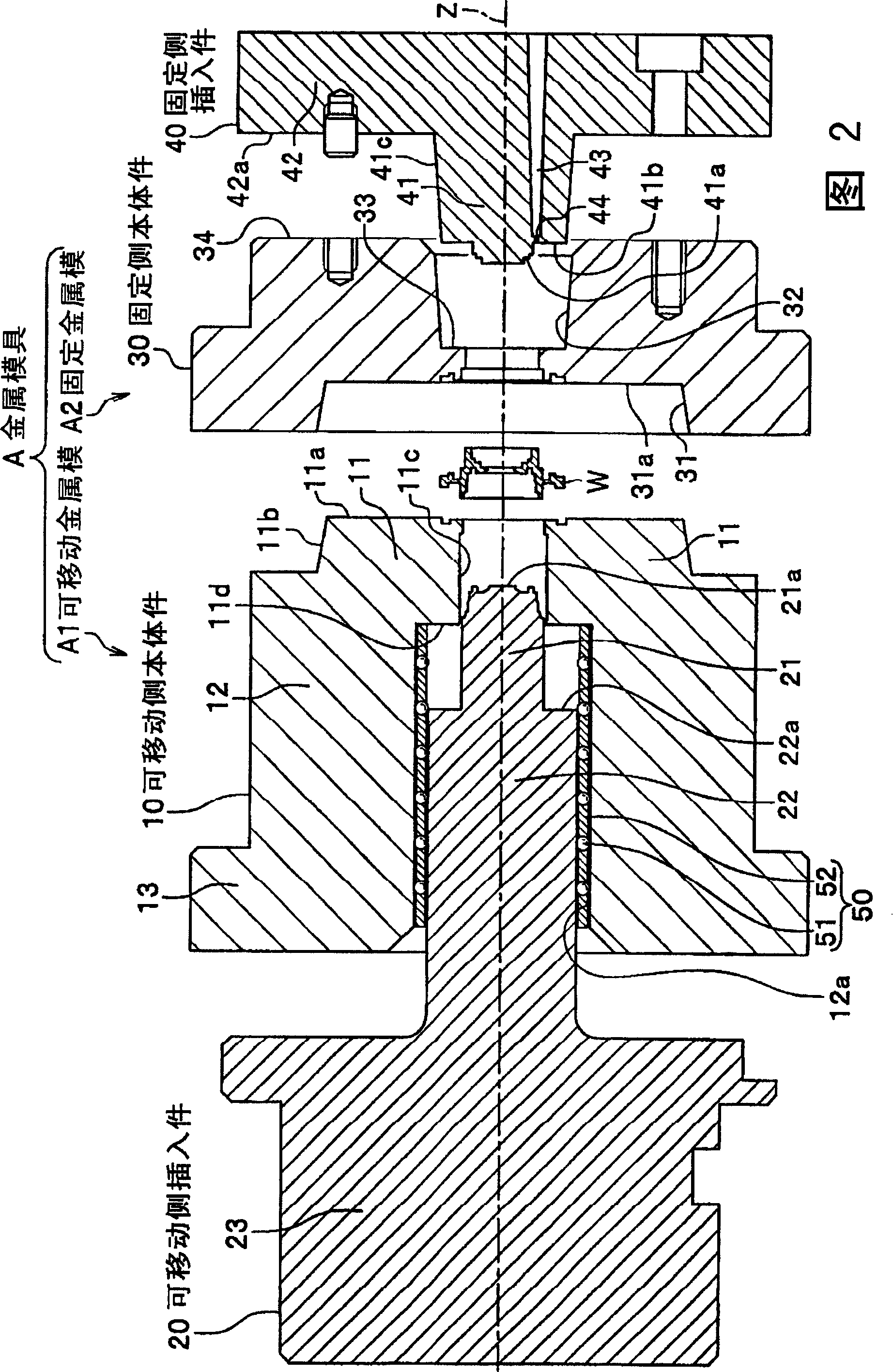
[0038] As shown in FIGS. 1 and 2 , a forming metal mold A according to the first embodiment includes a movable metal mold A1 as a first metal mold and a fixed metal mold A2 as a second metal mold. The molding metal mold A is a mold used for injection molding such as but not limited to a tubular molded article W. The molding metal mold A of the present invention can be particularly preferably used to manufacture molded articles requiring high shape accuracy, such as optical lenses and optical parts such as mirror frames for supporting optical lenses, and in this case, the movable metal mold The mutual positional relationship between A1 and fixed metal mold A2 is particularly important.

[0039] The movable metal mold A1 includes a movable side body member 10 as a first body member and a movable side insert 20 as a first insert. The fixed metal mold A2 inclu...

no. 2 example

[0064] Below, see Figure 4 A second embodiment of the present invention is described as a modified example of the first embodiment. Figure 4 is a sectional view of a forming metal mold according to the second embodiment. The same parts as those of the first embodiment are denoted by the same reference numerals, and their descriptions are omitted.

[0065] Such as Figure 4 As shown, the forming metal mold B according to the second embodiment includes a movable metal mold B1 and a fixed metal mold B2.

[0066] The movable metal mold B1 includes a movable side body part 10' and a movable side insert part 70. In the molding metal mold A of the first embodiment, the movable-side body member 10 and the movable-side insert 20 are relatively positioned by means of linear bearings 50 to be slidably (movable) assembled with each other. In contrast, in the moving metal mold B1, the relative positioning between the movable side body member 10' and the movable side insert 70 is achieve...


PUM


Abstract

The invention aims to produce a mould with high precision shape. The invention provides a forming metal die which is provided with a movable metal die (a first metal die) and a fixed metal die (a second metal die); a cavity, where the mould is made, is restricted between the movable metal die and the fixed metal die; the movable metal die is provided with a first convex cone which becomes thinnerfacing to the fixed metal die. The fixed metal die is provided with a first concave cone which can be assembled with the first convex cone. The first convex cone and the first concave cone are assembled in this way, namely when the first convex cone and the first concave cone are mutually assembled, corresponding conical surfaces are mutually propped at first; then the clamping forces of the movable metal die and the fixed metal die respectively lead the end surface and the bottom surface of the movable metal die and the fixed metal die, which can encircle the cavity, to be propped with each other. The forming metal die is applied to the mould made by injection forming.

Description

technical field [0001] The present invention relates to a forming metal mold, and in particular, to a forming metal mold capable of improving the shape accuracy of a molded product. Background technique [0002] In general, in producing molded articles having the same shape, for example, a method of pouring a material such as molten resin into a molding metal mold and extruding the material in the molding metal mold is used. A molding metal mold is provided with a cavity having convex and concave portions opposite to those of the molded articles to form the shape of the molded articles. To pour material into a cavity, a forming metal mold is divided into two or more parts at a parting line passing through the cavity. [0003] Although separate metal molds have a positioning structure for positioning using a pair of molds, when positioning is simply achieved by fitting a pin in a hole, it is necessary to make a clearance fit between the pin and the hole in order to smoothly ...

Claims


Application Information

Patent Timeline
Patent Type & Authority Applications(China)
IPC IPC(8): B29C33/30B29C45/26B29C45/00B29L11/00
Inventor 渡边清一繁定启司佐伯达彦御园生和敏
Owner FUJIFILM CORP
Why Eureka
Try Eureka