

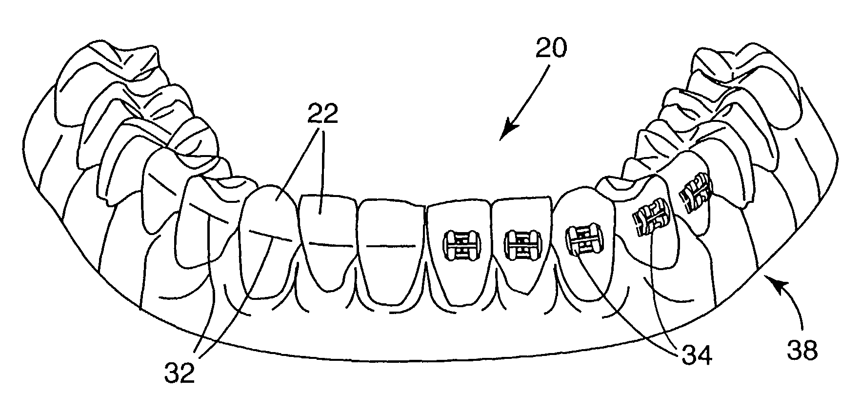
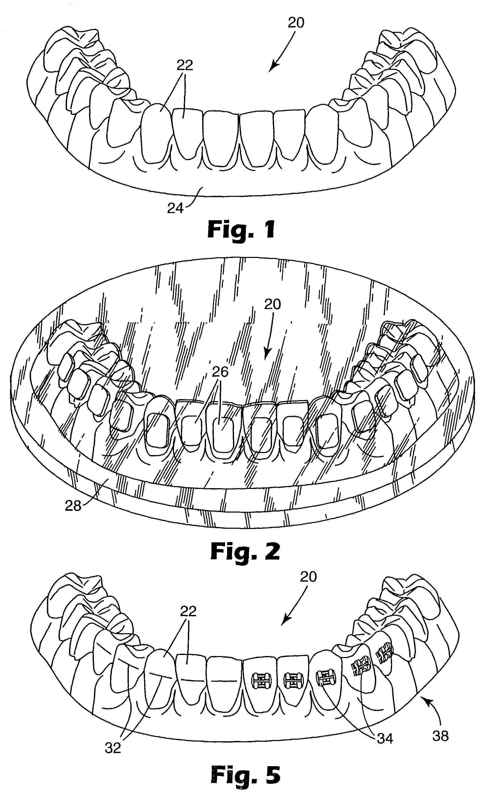
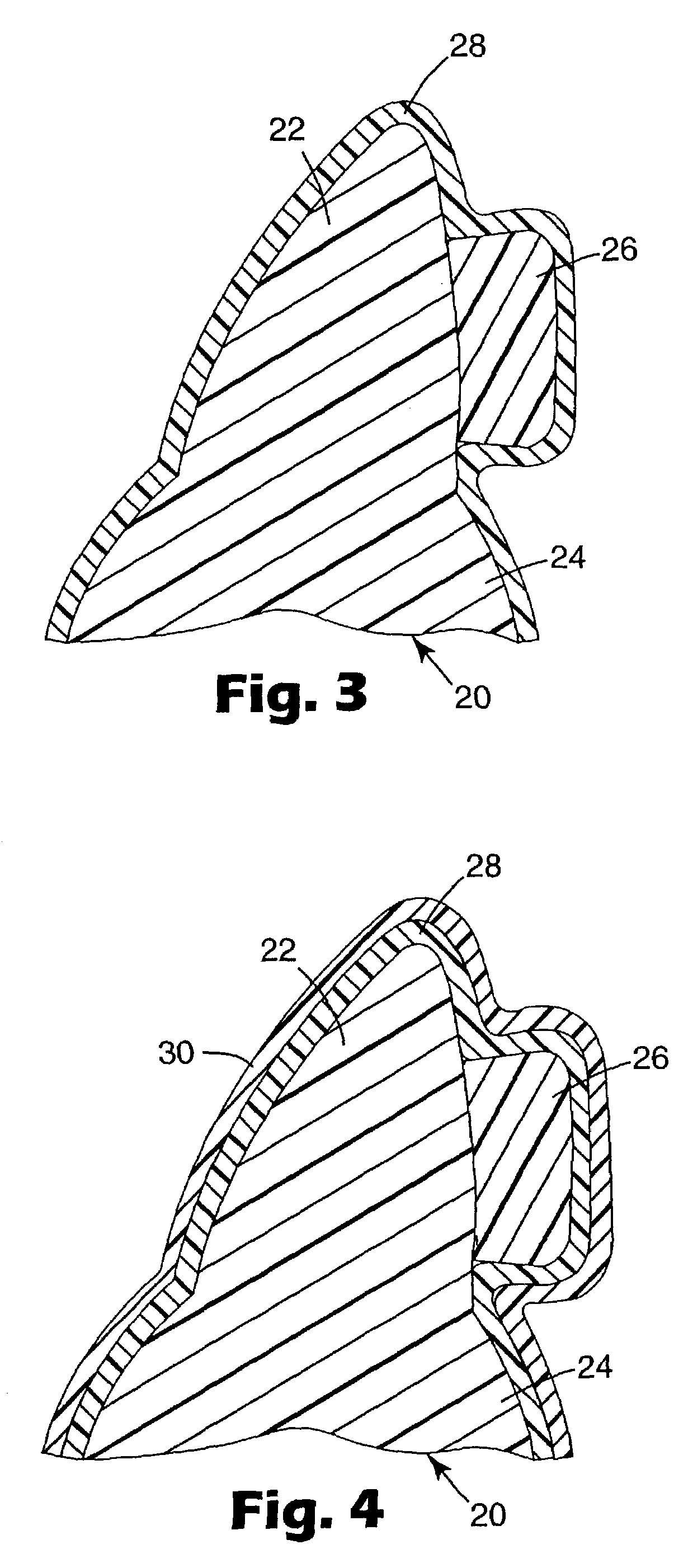
Orthodontic appliances having a contoured bonding surface
a bonding surface and orthodontic technology, applied in the field of orthodontic appliances, can solve the problems of inability to meet unaesthetic metal bands, and inability to use bands made of non-metallic materials, etc., to achieve the effect of improving the bonding surface, ensuring the shape of the patient's tooth structure, and ensuring the fi
- Summary
- Abstract
- Description
- Claims
- Application Information
AI Technical Summary
Benefits of technology
Problems solved by technology
Method used
Image

Examples
example
[0134]A test was conducted to compare the surface roughness of a sample of hardened modeling stone to the surface roughness of a sample of hardened epoxy resin. A stone sample was made by preparing a quantity of Quickstone brand laboratory stone (from Whip Mix Corporation) according to the manufacturer's directions. The stone preparation was then placed in a recess of a polypropylene substrate and allowed to harden.
[0135]A surface roughness tester (model no. SJ-301, from Mitutoyo Corporation, Kanagawa, Japan) was used at five distinct locations of the hardened stone to determine surface roughness. At the five locations, the hardened stone had an average surface roughness of 53.16 micro-inch (microinch Ra), with a standard deviation of 4.22.
[0136]The surface roughness test was repeated as described above, except that epoxy was used instead of modeling stone. The epoxy was the E-CAST F-82 resin and No. 302 hardener, from United Resin Corporation, as described above. At five locations,...
PUM
| Property | Measurement | Unit |
|---|---|---|
| thickness | aaaaa | aaaaa |
| distance | aaaaa | aaaaa |
| distance | aaaaa | aaaaa |
Abstract
Description
Claims
Application Information