Fabricated cast-in-place combined beam structure

A composite beam and prefabricated technology, applied to truss structures, joists, girders, etc., can solve problems such as damage, inability to prefabricate beams and core beams, and affect project quality, so as to achieve the effect of strengthening the joint surface

Pending Publication Date: 2019-10-15
JIANGXI THE SECOND CONSTR +1
View PDF0 Cites 0 Cited by
  • Summary
  • Abstract
  • Description
  • Claims
  • Application Information

AI Technical Summary

Problems solved by technology

[0002] In recent years, my country has actively explored the development of prefabricated buildings. In this field, there is a prefabricated cast-in-place composite beam-slab structure. The composite beam of this structure is composed of side prefabricated beams and middle cast-in-place core beams. The joint surface between the prefabricated beam and the cast-in-place core beam in the beam is a weak surface, which is easily damaged and cannot make the prefabricated beam and the core beam work together, thus affecting the quality of the project

Method used


Image

  • Fabricated cast-in-place combined beam structure
  • Fabricated cast-in-place combined beam structure
  • Fabricated cast-in-place combined beam structure

Examples


Embodiment Construction

[0025] The following will clearly and completely describe the technical solutions in the embodiments of the present invention with reference to the accompanying drawings in the embodiments of the present invention. Obviously, the described embodiments are only some, not all, embodiments of the present invention. Based on the embodiments of the present invention, all other embodiments obtained by persons of ordinary skill in the art without making creative efforts belong to the protection scope of the present invention.

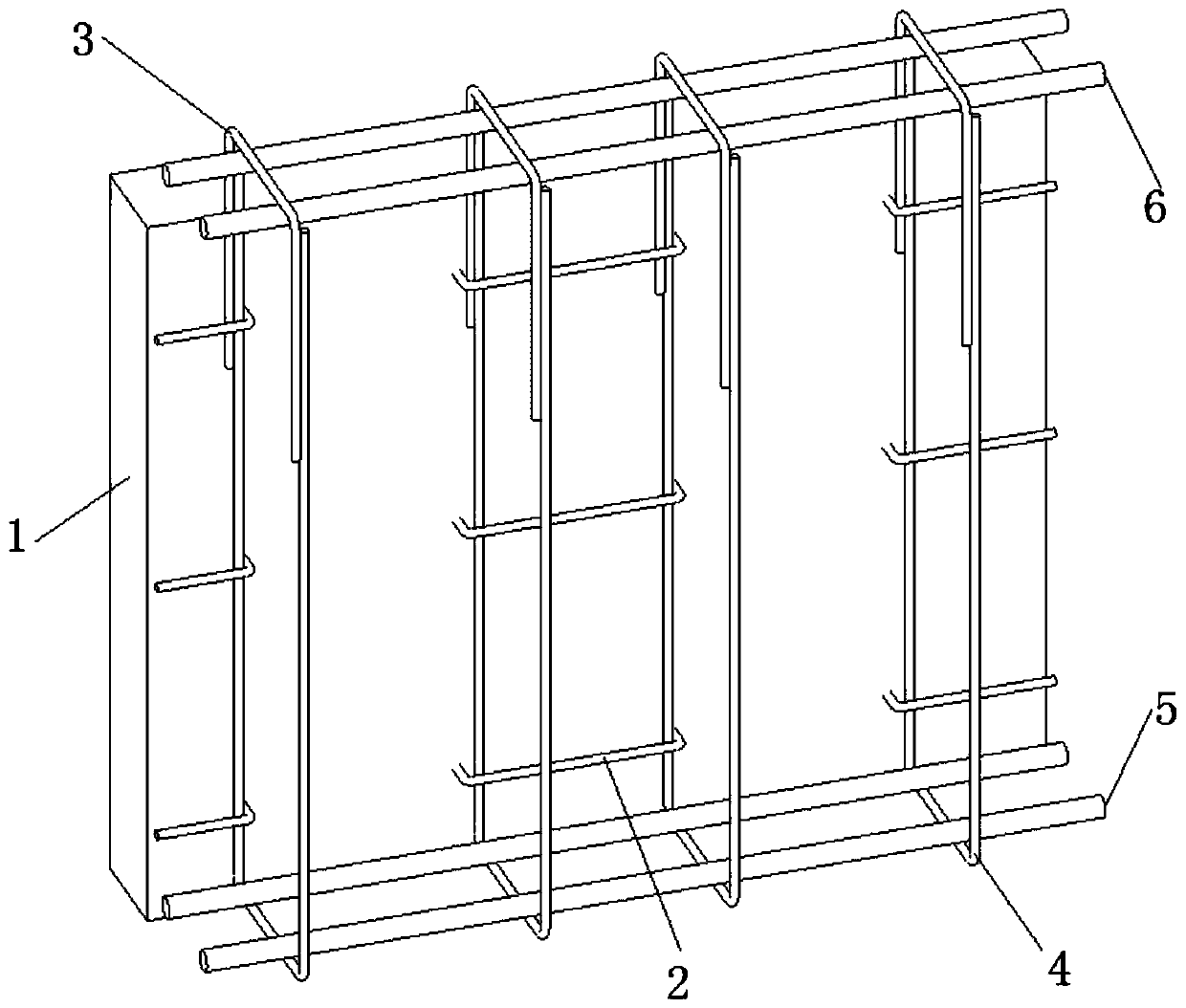
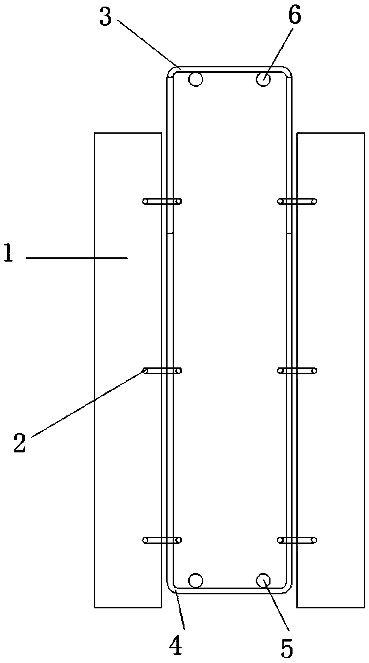
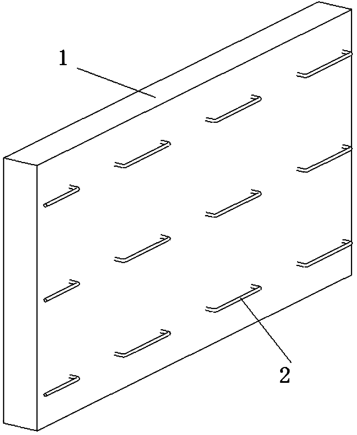
[0026] The embodiment of the present invention discloses an assembled cast-in-place composite beam structure, which strengthens the joint surface between the prefabricated side sill plate and the cast-in-place core beam, so that the prefabricated beam and the cast-in-place core beam in the composite beam can better cooperate with each other. work to strengthen the bonding surface.

[0027] The invention discloses an assembled cast-in-place composite beam struc...


PUM


Abstract

The invention discloses a fabricated cast-in-place combined beam structure. The fabricated cast-in-place combined beam structure comprises a cast-in-place core beam and prefabricated side beam plateslocated on the two sides of the cast-in-place core beam; each prefabricated side beam plate comprises a prefabricated plate and bonding surface constructional steel bars, and the bonding surface constructional steel bars are connected to the surface of one side of the corresponding prefabricated plates in an embedded manner; the cast-in-place core beam comprises a cast-in-place beam body, upper opening hoops, lower opening hoops, core beam bottom ribs and core beam surface ribs; the upper opening hoops are located on the top of the cast-in-place beam body, the lower opening hoops are located at the bottom of the cast-in-place beam body, and openings of the upper opening hoops and openings of the lower opening hoops are oppositely arranged and connected to form annular hoops; and the core beam bottom ribs are located at the inner bottoms of the annular hoops, and the core beam surface ribs are located on the inner tops of the annular hoops. According to the fabricated cast-in-place combined beam structure, the bonding surfaces between the prefabricated side beam plates and the cast-in-place core beam are enhanced, and therefore the prefabricated beam and the cast-in-place core beamin the combined beam can better jointly work to enhance the bonding surfaces.

Description

technical field [0001] The invention relates to the technical field of construction engineering, and more specifically relates to an assembled cast-in-place composite beam structure. Background technique [0002] In recent years, my country has actively explored the development of prefabricated buildings. In this field, there is a prefabricated cast-in-place composite beam-slab structure. The composite beam of this structure is composed of side prefabricated beams and middle cast-in-place core beams. The joint surface between the prefabricated beam and the cast-in-place core beam in the beam is a weak surface, which is easily damaged and cannot make the prefabricated beam and the core beam work together, thus affecting the quality of the project. Contents of the invention [0003] In view of this, the present invention provides an assembled cast-in-place composite beam structure, aiming to solve at least one of the technical problems in the prior art. [0004] In order to ...

Claims


Application Information

Patent Timeline
Patent Type & Authority Applications(China)
IPC IPC(8): E04C3/20
CPCE04C3/20
Inventor 王志龙周俊罗文升范海飞蔡民袁林娜黄道光刘瑜
Owner JIANGXI THE SECOND CONSTR
Why Eureka
Try Eureka