Roof ventilating fan

A technology for exhaust fans and shutters, which is applied to components of pumping devices for elastic fluids, non-variable-capacity pumps, pump devices, etc., can solve the problems of small opening angle and inability to obtain large exhaust volume, etc. To achieve the effect of increasing the exhaust air volume

Inactive Publication Date: 2008-05-28
KAMAKURA CORPORATION
View PDF0 Cites 8 Cited by
  • Summary
  • Abstract
  • Description
  • Claims
  • Application Information

AI Technical Summary

Problems solved by technology

That is, when the interval between the cover and the main body has to be reduced due to the necessity of preventing the inflow of rainwater, etc., the left and right plate-shaped louvers on each butterfly louver are all flat plates, so the plate-shaped louvers on each piece When the air duct is opened due to the wind pressure caused by the rotation of the fan, the opening angle is small, and a large air volume cannot be obtained.

Method used


Image

  • Roof ventilating fan
  • Roof ventilating fan
  • Roof ventilating fan

Examples


Embodiment

[0019] Hereinafter, examples of the present invention will be described.

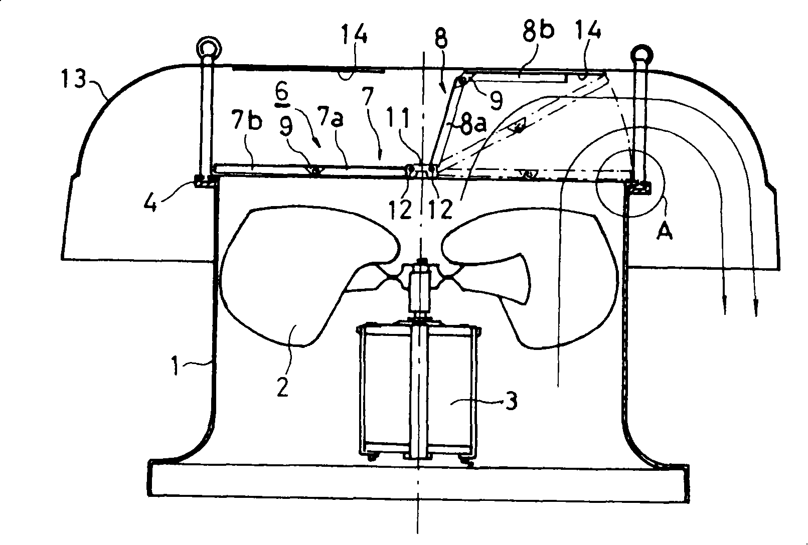
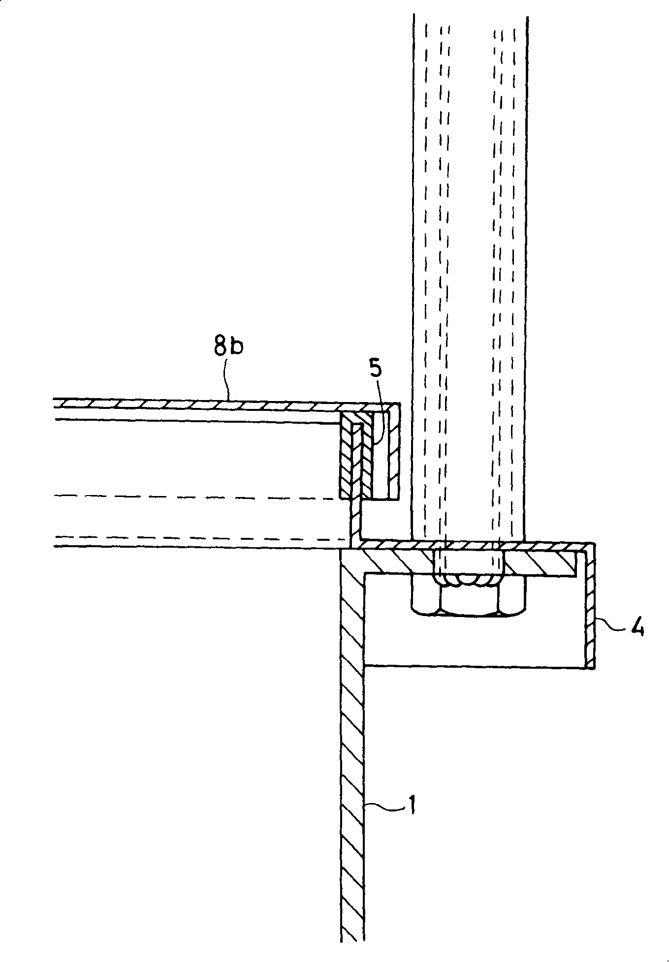
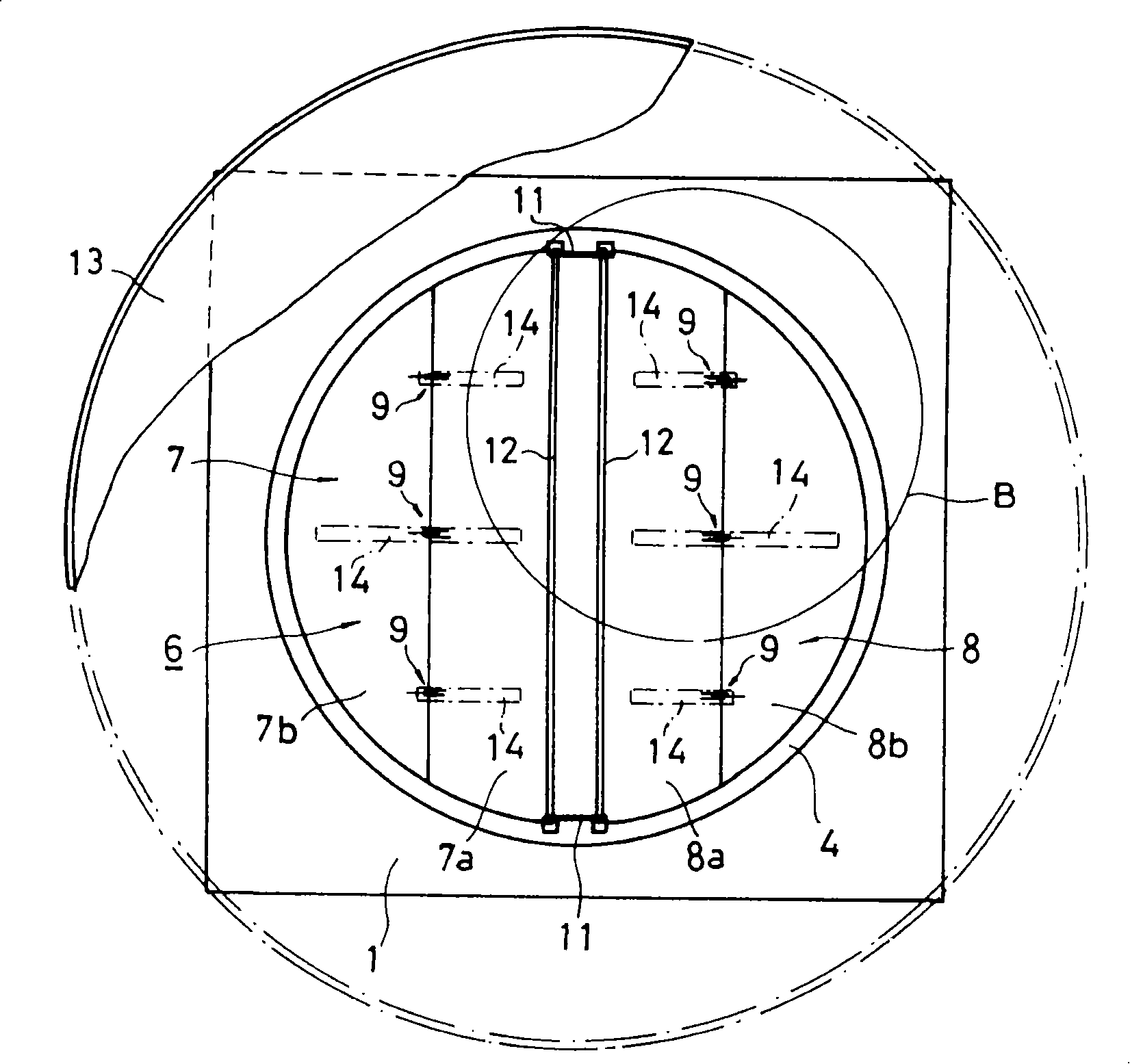
[0020] figure 1 It is the front view of the middle longitudinal section of the embodiment of the present invention, figure 2 yes figure 1 Enlarged view of part A in, image 3 It is a partially cutaway top view showing an embodiment of the present invention, Figure 4 yes image 3 Enlarged view of part B in, Figure 5 is an enlarged view of the pivoting part of the base of the plate shutter, Figure 6 It is a top view of hinges and springs for flexion and extension of plate shutters, Figure 7 It is an explanatory diagram of the opening and closing operation of the plate-shaped shutter.

[0021] Among the figure, 1 is the cylindrical main body that is opened up and down. 2 is the fan that is arranged in the inside of the above-mentioned main body 1 and rotates by the motor 3 .

[0022] Reference numeral 4 denotes a louver mounting frame fixed to the upper opening of the main body 1 . In additi...


PUM


Abstract

The invention relates to a roof exhaust fan. The invention is used for resolving a problem that the angle of a blind is increased to expand air displacement. Right and left blinds (7, 8) of each butterfly blind(6) are broken up into an inner side(7a, 8a) and an outside side(7b, 8b), which are linked with hinges(9, 9) in order to extend the inner side(7a, 8a) and the outside side(7b, 8b), and a spring(10) with suitable flexibility leans in order to extend.

Description

technical field [0001] The invention relates to a roof exhaust fan arranged on the roof. Background technique [0002] A roof exhaust fan used on the roof in the past includes: a cylindrical main body that is open up and down; a fan that is installed inside the main body and rotated by a motor; The louver structure is composed of a pivot pivoted on the base at the free end side of the outside, and at the same time it is rotated in the vertical direction. The left and right pair of plate-shaped louvers are installed with the louver installation frame on the upper opening of the main body; according to the specified An inverted dish-shaped cover is installed above the main body at intervals. [0003] However, such a roof exhaust fan has the following problems. That is, when the interval between the cover and the main body has to be reduced due to the necessity of preventing the inflow of rainwater, etc., the left and right plate-shaped louvers on each butterfly louver are al...

Claims


Application Information

Patent Timeline
Patent Type & Authority Applications(China)
IPC IPC(8): F04D25/14F04D29/52
Inventor 堀江威史
Owner KAMAKURA CORPORATION
Why Eureka
Try Eureka