Image projection device and rear projection type display device
A technology of projection device and display device, applied in projection device, image communication, projector with built-in screen/external screen, etc., can solve the problems of obstructing objects, observation of laser, etc., to improve safety and increase expansion angle , The effect of realizing the miniaturization of the device
- Summary
- Abstract
- Description
- Claims
- Application Information
AI Technical Summary
Problems solved by technology
Method used
Image

Examples
Embodiment approach 1
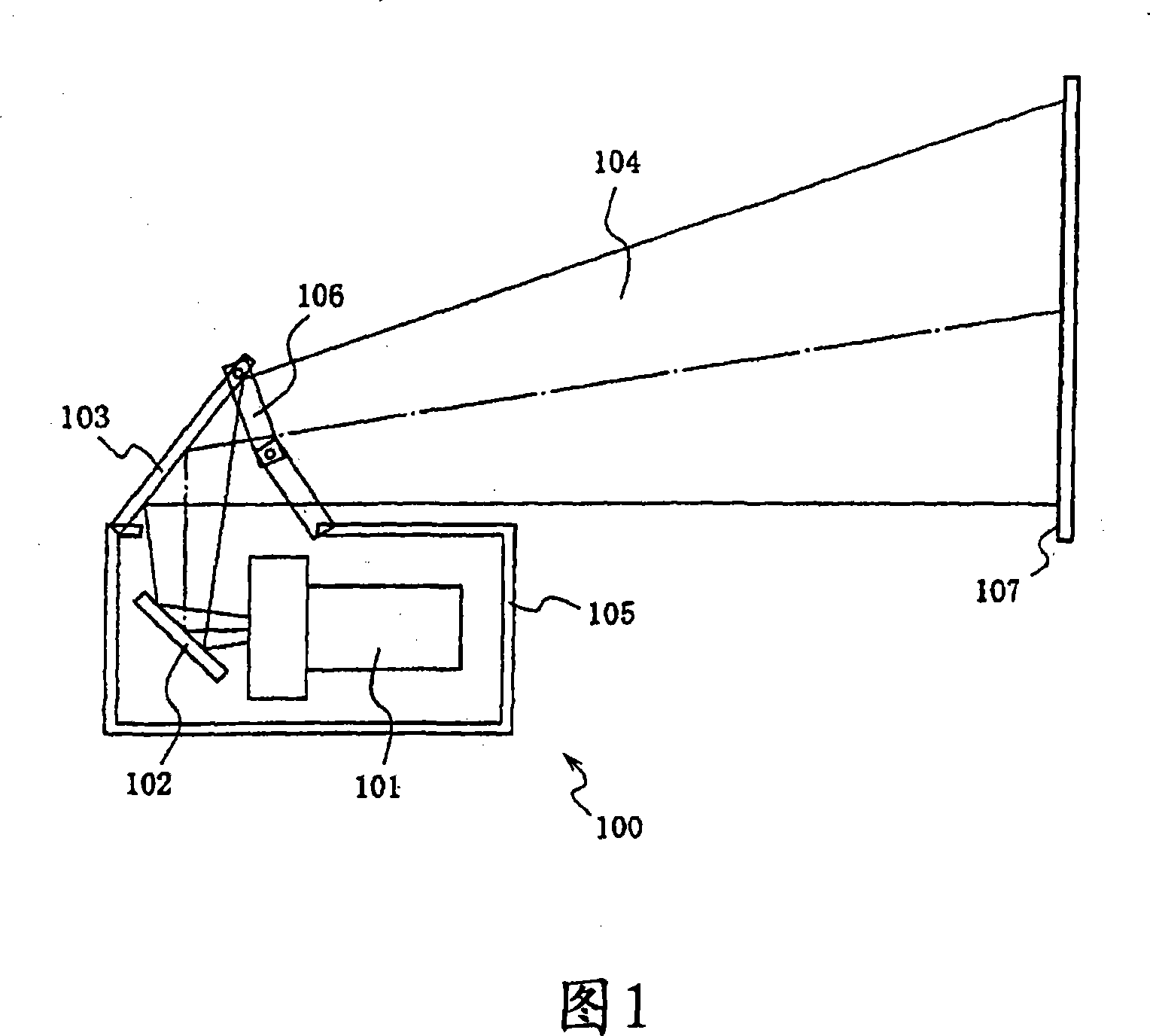
[0090] FIG. 1 is a configuration diagram of an image projection device 100 according to Embodiment 1 of the present invention.
[0091] In FIG. 1 , an image projection device 100 consists of an image projection unit 101 that projects laser light, a first turning mirror 102 that bends the laser light emitted from the image projection unit 101 at first, and a first turning mirror 102 that passes the laser light emitted from the projection lens. The second folding mirror 103 reflected on the screen, the folding holding frame 106 and the frame body 105 constitute.
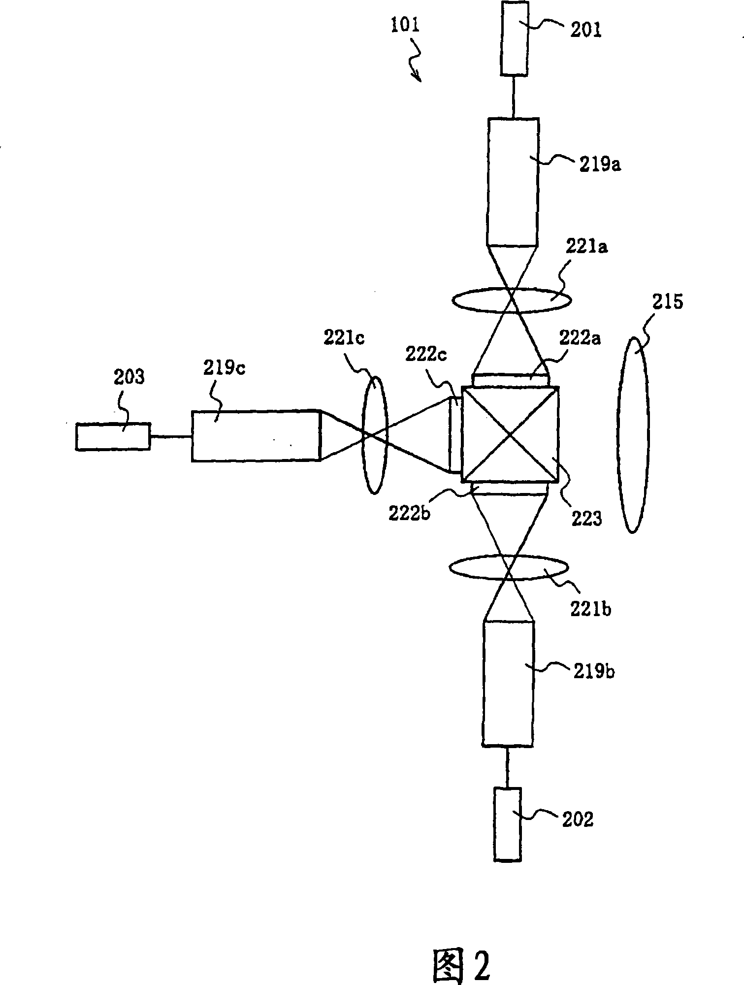
[0092] The image projection unit 101 is preferably composed of a laser light source, a two-dimensional light modulation element such as a liquid crystal panel or a micro-mirror array, and a projection lens. Alternatively, the image projecting unit 101 may also be composed of a laser light source, a one-dimensional light modulation element, a converging lens, and an optical scanning element.
[0093] Next, the image pr...
Embodiment approach 2
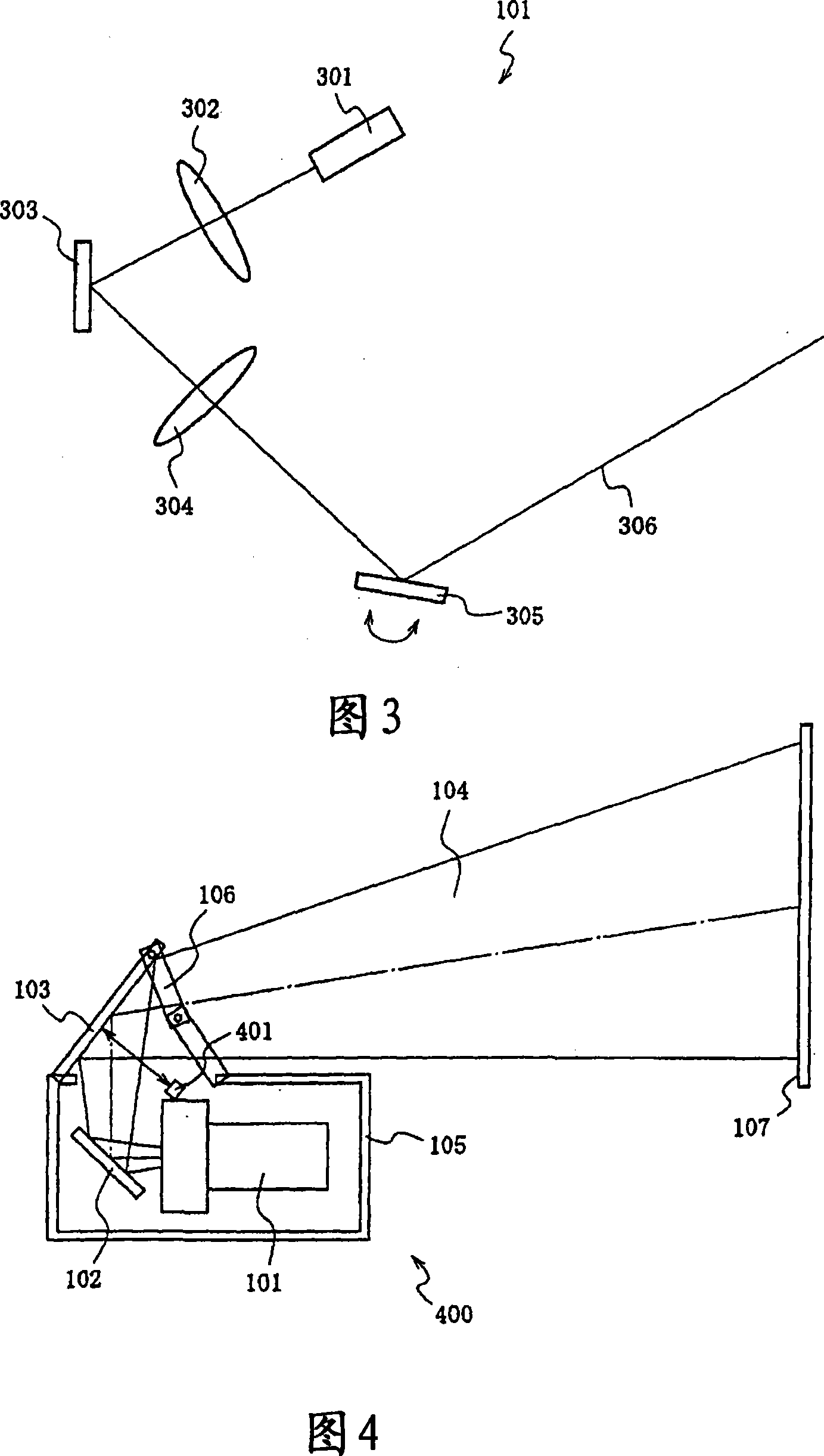
[0114] 6 is a configuration diagram of an image projection device according to Embodiment 2 of the present invention, and the same reference numerals are used for the same elements as those in FIG. 1, and their descriptions are omitted. Also, in Embodiment 2, since the image projection device 101 uses a one-dimensional or two-dimensional spatial light modulator and has the same configuration as in FIGS. 2 and 3 , description thereof will be omitted.
[0115] An image projection device 600 according to the second embodiment is different from the first embodiment in that a restriction plate 601 is provided instead of the holding frame 106 described in the first embodiment.
[0116] In FIG. 6 , the limiting plate 601 is preferably made of a transparent acrylic plate having a high transmittance to the projected light 104 and is preferably larger than the cross-sectional area of the projected light 104 . In addition, the second turning mirror is provided so as to maintain a prede...
Embodiment approach 3
[0128] 7 is a configuration diagram of a rear projection display device according to Embodiment 3 of the present invention.
[0129] In FIG. 7, the rear projection type display device 700 related to the third embodiment has its laser emission surface facing the screen 710 side, and an image projection unit 701 which projects laser light, bends the laser light emitted from the image projection unit 701 to an image. The first turning mirror 707 on one side of the projection unit 701 reflects the laser light reflected by the first turning mirror 707 to the screen 710, and the second turning mirror 708 that emits the laser light from the image projecting unit 701 to the screen 710 is transmitted by the laser beam from the image projecting unit. 701 is composed of a screen 710 on which laser images are displayed and a frame 711 that houses them.
[0130] Like image projection unit 101 in Embodiment 1, image projection unit 701 in Embodiment 3 is preferably composed of a laser light...
PUM
 Abstract
Description
Claims
Application Information
 - R&D
- Intellectual Property
- Life Sciences
- Materials
- Tech Scout
- Unparalleled Data Quality
- Higher Quality Content
- 60% Fewer Hallucinations
Browse by: Latest US Patents, China's latest patents, Technical Efficacy Thesaurus, Application Domain, Technology Topic, Popular Technical Reports.
© 2025 PatSnap. All rights reserved.Legal|Privacy policy|Modern Slavery Act Transparency Statement|Sitemap|About US| Contact US: help@patsnap.com