
Method and device for processing particulates material bed layer

A particulate material, air flow technology, applied in the field of cooling an air-supported particulate material bed, can solve problems such as the inability to obtain heat exchange benefits, the unsatisfactory operation of the clinker bed, and the reduction of flow characteristics.

Active Publication Date: 2008-06-25
TIANJIN CEMENT IND DESIGN & RES INST
View PDF2 Cites 2 Cited by
  • Summary
  • Abstract
  • Description
  • Claims
  • Application Information

AI Technical Summary

Problems solved by technology

When utilizing the on / off device of patent 1221984, the clinker bed is clinker due to the same chain reaction as described above in patent PCT / US96 / 02971 - with reduced flow characteristics at reduced bed flow resistance. layers will not work satisfactorily
In other words, all on / off devices will eventually close and the heat exchange benefits associated with flow compensation will not be gained

Method used


Image

  • Method and device for processing particulates material bed layer
  • Method and device for processing particulates material bed layer
  • Method and device for processing particulates material bed layer

Examples


Embodiment Construction

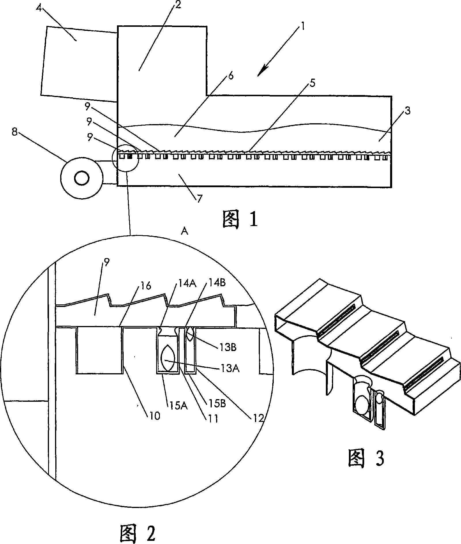
[0039] FIG. 1 shows a cooler 1 comprising an inlet port 2 and an outlet port 3 . The cooler is connected to the rotary kiln 4 and receives the hot material to be cooled from the rotary kiln 4 . The material from the rotary kiln falls onto a distribution floor 5 provided in the cooler 1 and is conveyed as a layer 6 of material on the distribution floor 5 from the inlet end 2 of the cooler 1 to the outlet by a conveying device (not shown) End 3. The transport device may be, but not limited to, a reciprocating grate, a reciprocating grate or a walking floor principle. Below the distribution floor 5, the cooler 1 comprises one or more compartments 7, each compartment being supplied with cooling air from a blower device. The compartment 7 may be divided into a number of small compartments (not shown) in the longitudinal and transverse directions of the cooler, in which case each individual compartment is supplied with cooling air. The distribution base 5 is divided into a number...


PUM


Abstract

A bed of particulate material 6 is supported by an air distribution bottom 5. Under the distribution bottom 5 exist one or more compartments 7, which each being supplied with cooling air from a fan installation 8. The distribution bottom 5 is sectionalised in a number of smaller areas 9. Each smaller distribution area 9 is connected to the compartment 7 by ducts 10, 11 and 12. The one duct 10 does have a fixed orifice area. The ducts 11 and 12 do have floaters 13A / 13B end stop 14A / 14B and bottom support 15A / 15B. It is hereby obtained that the total pressure loss across the air distribution bottom can be reduced, and so that the flow of the treatment air through the material bed is distributed in a desirable manner across the entire air distribution bottom regardless of the composition of the material bed and the distribution thereon, and optimal heat exchange efficiency is obtained.

Description

technical field [0001] The present invention relates to a method for cooling a bed of particulate material supported by air, while the particulate material is conveyed horizontally from the inlet end to the outlet end of the air distribution floor, air is conveyed via ducts from one or more lower compartments to Conveys in a partitioned manner and is directed upwards through the air distribution floor and material bed. [0002] The invention also relates to an air flow device for carrying out the method of the invention. Background technique [0003] An example of a device comprising an air distribution floor is a cooler for cooling eg cement clinker. In such coolers the main objective is to achieve a satisfactory degree of heat exchange between the clinker and the cooling air so that most of the heat energy contained in the hot clinker is returned to the kiln system in the cooling air , while the clinker exits the cooler at a temperature very close to ambient temperature....

Claims


Application Information

Patent Timeline
Patent Type & Authority Applications(China)
IPC IPC(8): F28C3/16F28F27/02F27D15/02C04B7/47
CPCF28F27/02F27D15/0213C04B7/47F27B7/383F28C3/16
Inventor M·J·丰斯
Owner TIANJIN CEMENT IND DESIGN & RES INST
Learn More