Supercharge Your Innovation With Domain-Expert AI Agents!

Rotary encoding switch

A rotary coding switch, switch-level technology, applied in the direction of code conversion, analog-to-digital converter, analog-to-digital conversion, etc., can solve the problems of limited accuracy, complex set value and cost, and achieve high-resolution effect

Inactive Publication Date: 2008-06-25
SIEMENS AG
View PDF0 Cites 0 Cited by
  • Summary
  • Abstract
  • Description
  • Claims
  • Application Information

AI Technical Summary

Problems solved by technology

Although resistance potentiometers can theoretically be set extremely finely, due to factors such as nonlinearity, mechanical tolerances, and reading errors, in practice, the accuracy that can be achieved in setting values ​​​​is very limited.
Therefore, when using a resistance potentiometer, a complex and costly calibration of the setpoint is generally necessary

Method used


Image

  • Rotary encoding switch
  • Rotary encoding switch
  • Rotary encoding switch

Examples


Embodiment Construction

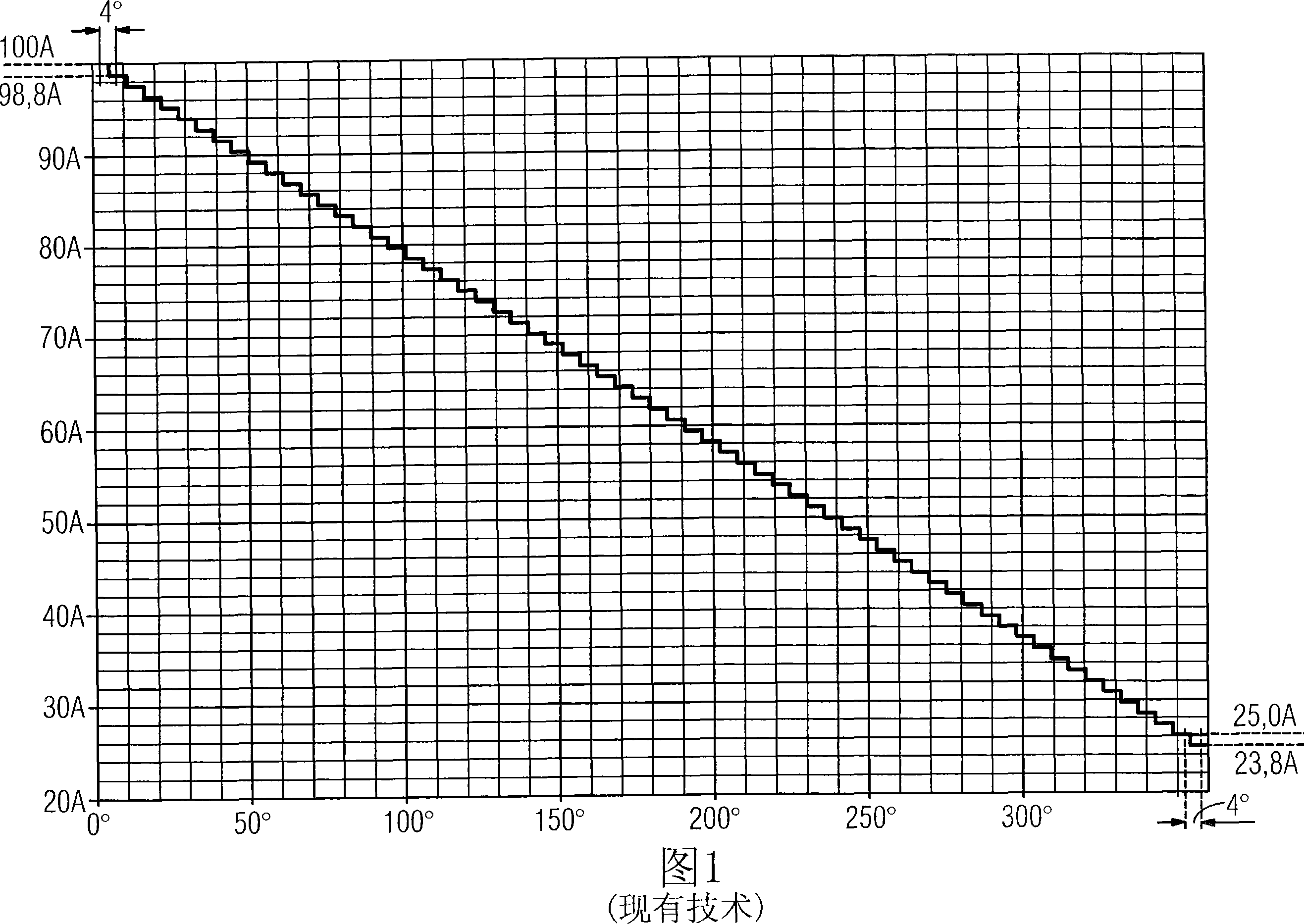
[0018] The difference between n-stage (for example n=16) rotary encoding switches disclosed in the prior art is that the distance between each switch stage is constant. The example shown in FIG. 1 employs such conventional rotary-encoded switches, where 64 switching stages have been used here for better comparison with the solution of the invention. A rotary-encoded switch comprising 64 switching stages has not been disclosed so far.

[0019] In a 64-stage rotary-encoded switch including a circular code disc, the constant spacing between each switching stage is approximately 5.63°. If this rotary encoding switch is used as a current setting element in an overload relay, a dial with current markings and a setting arrow are required. The installation of dials and setting arrows on rotary coding switches is always subject to manufacturing tolerances. Experience shows that manufacturing tolerances lie within a range of not more than + / - 4°.

[0020] In this example (see Figure ...


PUM


Abstract

The invention relates to a rotary encoding switch such as used in the function setting for relays or similar. According to the invention, a particularly secure function setting for relays or similar may be achieved by means of a rotary encoding switch with a number of switch stages with separations between the switch stages which are not constant.

Description

technical field [0001] The invention relates to a rotary coding switch, for example for setting functions in relays or the like. Background technique [0002] It is known to use resistance potentiometers to set various parameters such as current, voltage or time. With the help of a resistance potentiometer, an analog resistance change can be tapped off and used directly in an analog circuit, e.g. to vary the gain. In digital circuits, an analog resistance change can be read in by means of an analog / digital converter and then processed. Although resistance potentiometers are theoretically capable of extremely fine settings, in practice they can achieve very limited accuracy in setting values ​​due to factors such as nonlinearity, mechanical tolerances, and reading errors. When using resistance potentiometers, a complex and costly calibration of the setpoint is therefore generally necessary. Contents of the invention [0003] The object of the invention is to perform a pa...

Claims


Application Information

Patent Timeline
IPC IPC(8): H03M1/28
CPCH03M1/1235H03M1/285
Inventor 西格弗里德·诺伊曼尤维·韦斯
Owner SIEMENS AG
Features
  • R&D
  • Intellectual Property
  • Life Sciences
  • Materials
  • Tech Scout
  • Unparalleled Data Quality
  • Higher Quality Content
  • 60% Fewer Hallucinations
Learn More