Structure for reinforcing rigidity of vehicle body

A rigid, car body technology, applied in the superstructure, superstructure sub-assemblies, vehicle components, etc., to solve problems such as encountering difficulties and difficulties

Active Publication Date: 2008-07-02
MITSUBISHI MOTORS CORP
View PDF0 Cites 5 Cited by
  • Summary
  • Abstract
  • Description
  • Claims
  • Application Information

AI Technical Summary

Problems solved by technology

[0009] However, as described in Patent Document 1, when the structure that connects the upper surface of the spring cover 118 to the lower surface of the cowl top 120 is employed, the downwardly disposed part leading to the cowl top 120 is manufactured. Difficult problems encountered in the passage of space
[0010] Specifically, difficulties will be encountered when installing vehicle components (for example, the brake booster 121 shown in FIG. 4 ) in the downwardly disposed space of the cowl top 120 or when servicing them.

Method used


Image

  • Structure for reinforcing rigidity of vehicle body
  • Structure for reinforcing rigidity of vehicle body
  • Structure for reinforcing rigidity of vehicle body

Examples


Embodiment Construction

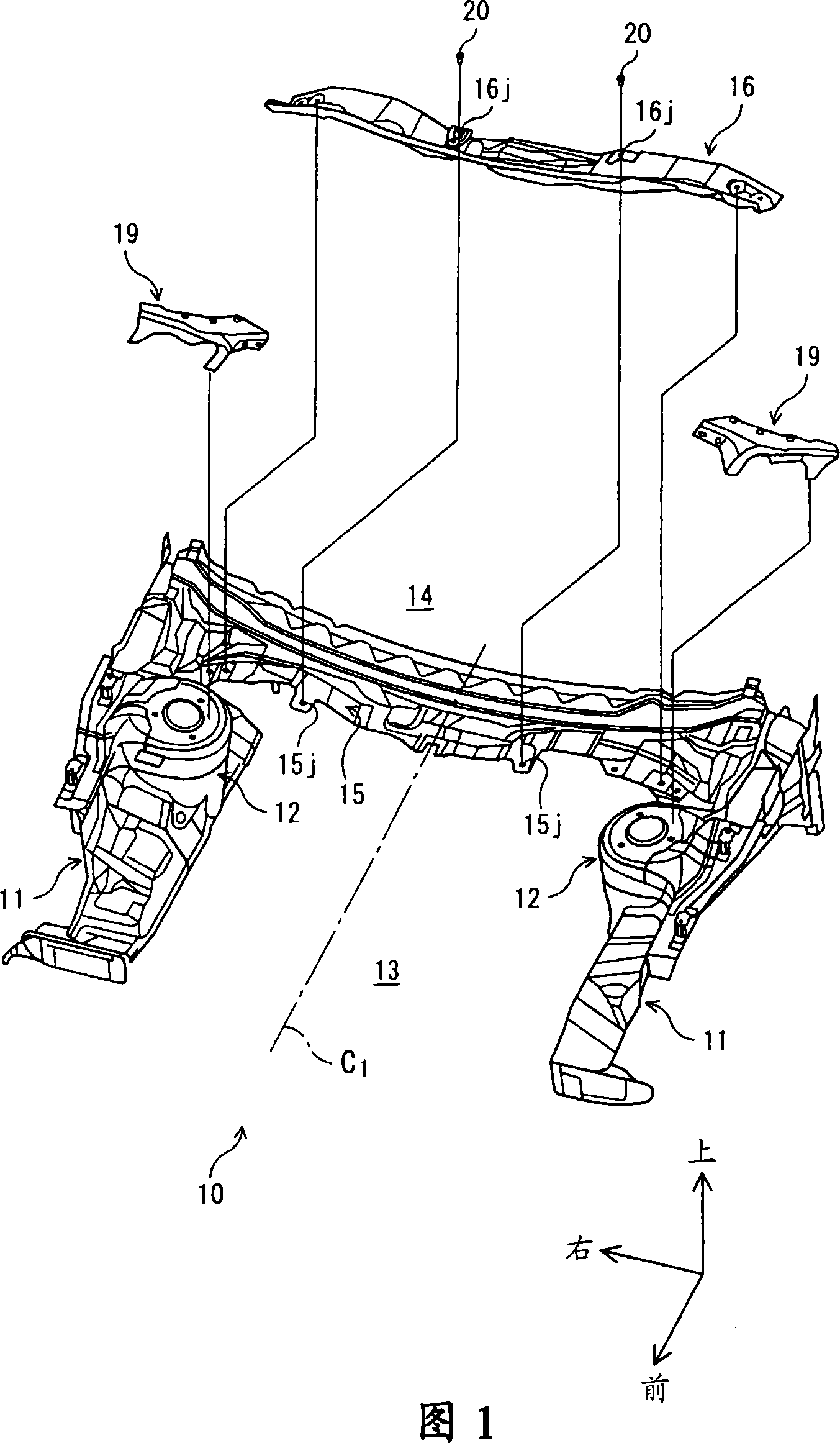
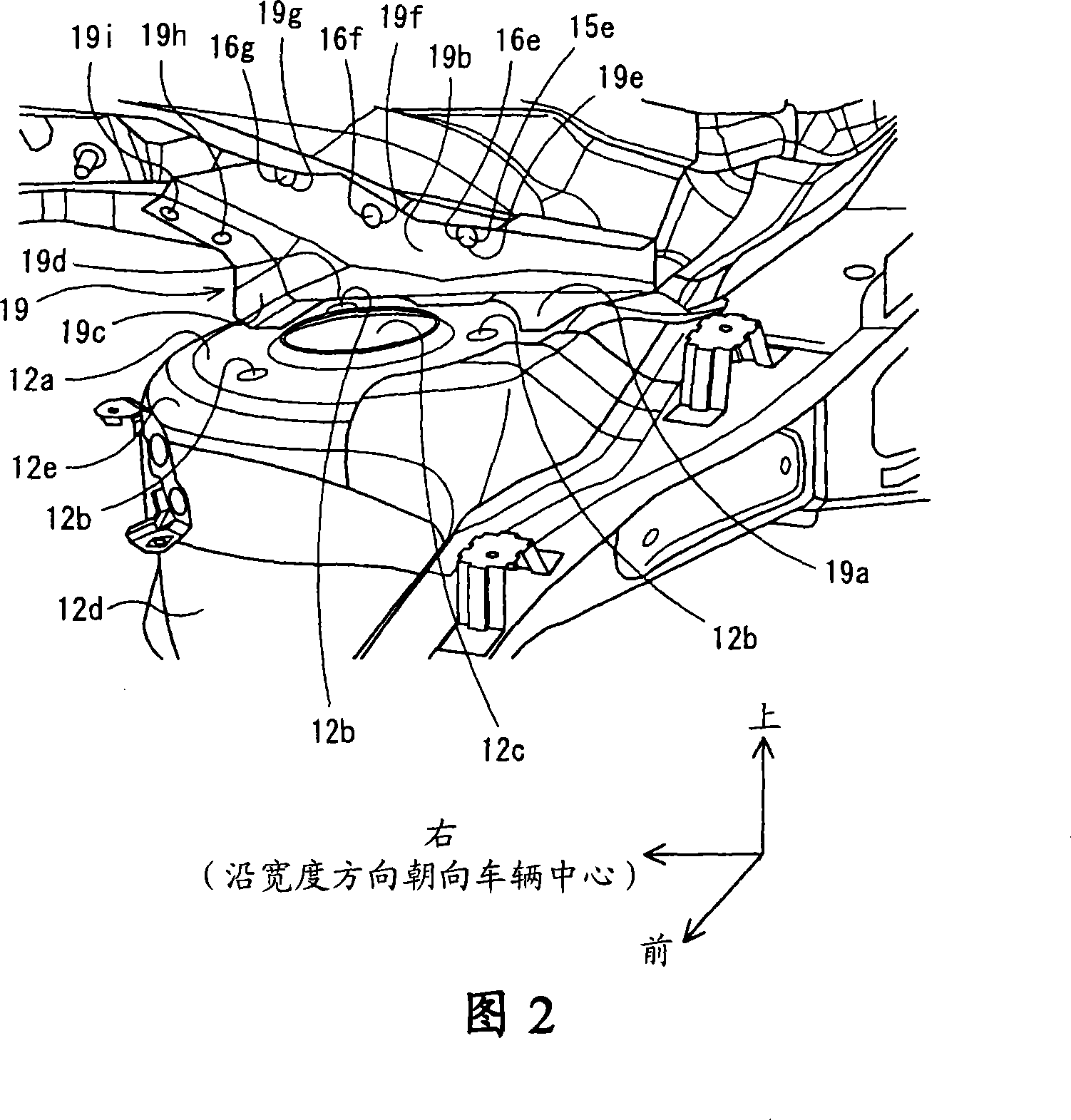
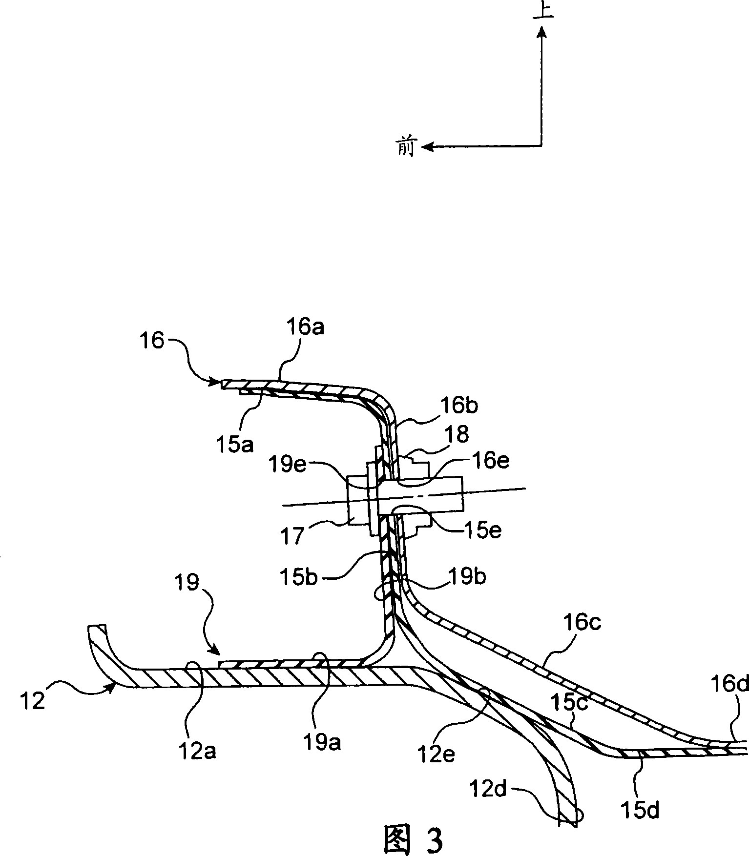
[0026] A structure for enhancing rigidity of a vehicle body of an embodiment of the present invention will be described below with reference to the accompanying drawings. 1 is a schematic perspective view showing a vehicle body constituting a front part of a vehicle; FIG. 2 is a schematic perspective view showing a configuration in the vicinity of a spring cover; and FIG. 3 is a schematic cross section showing a configuration in the vicinity of the spring cover view.

[0027] As shown in FIG. 1, the front of the vehicle 10 is mounted with an upper frame 11 extending in the longitudinal direction of the vehicle body 10 such that one upper frame is provided on the left side and the other upper frame is provided on the right side, Thereby forming part of the vehicle body.

[0028] The upper frames 11 are respectively provided with spring covers 12 .

[0029] Each spring cover 12 is a member formed in a cylindrical shape. The spring cover accommodates and supports the upper por...


PUM


Abstract

A structure for enhancing the rigidity of a vehicle body, comprising: a support member adapted to support an upper end of a suspension; a first member extending along the width direction of the vehicle body; a connecting reinforcement member fixed to the support member, and the first member The end portion is joined to the connection reinforcement; and the second piece extends in the width direction and is detachably fixed to the first piece and the connection reinforcement.

Description

technical field [0001] The present invention relates to a structure for enhancing the rigidity of a vehicle body. Background technique [0002] Structures have hitherto been known for reinforcing a part of the structure of the vehicle body, the so-called springhouse, which supports the suspension. The technique described in Patent Document 1 provided below refers to an example structure. [0003] The technique described in Patent Document 1 will be described by referring to FIG. 4 . FIG. 4 corresponds to FIG. 2 of Patent Document 1, and is a plan view of the front right side of the vehicle 100 when viewed from above. [0004] As shown in FIG. 4 , the vehicle 100 is mounted with a longitudinally extending upper frame 117 . FIG. 4 shows only the upper frame 117 provided on the right side of the vehicle 100 . However, a similar upper frame 117 is also provided on the left side of the vehicle 100 . [0005] A cowl top 120 is provided between the pair of upper frames 117 . ...

Claims


Application Information

Patent Timeline
Patent Type & Authority Applications(China)
IPC IPC(8): B62D25/08
Inventor 武本赖人鹤见修一
Owner MITSUBISHI MOTORS CORP
Why Eureka
Try Eureka