Method for determining the rotation speed of rotating shaft

A speed, rated technology used in the field of computer programming to solve problems such as inaccurate beats

Inactive Publication Date: 2008-07-02
ROBERT BOSCH GMBH
View PDF0 Cites 15 Cited by
  • Summary
  • Abstract
  • Description
  • Claims
  • Application Information

AI Technical Summary

Problems solved by technology

[0004] The problem with this type of method for data transmission is that only a relatively inaccurate beat is available in the sensor

Method used


Image

  • Method for determining the rotation speed of rotating shaft
  • Method for determining the rotation speed of rotating shaft
  • Method for determining the rotation speed of rotating shaft

Examples


Embodiment Construction

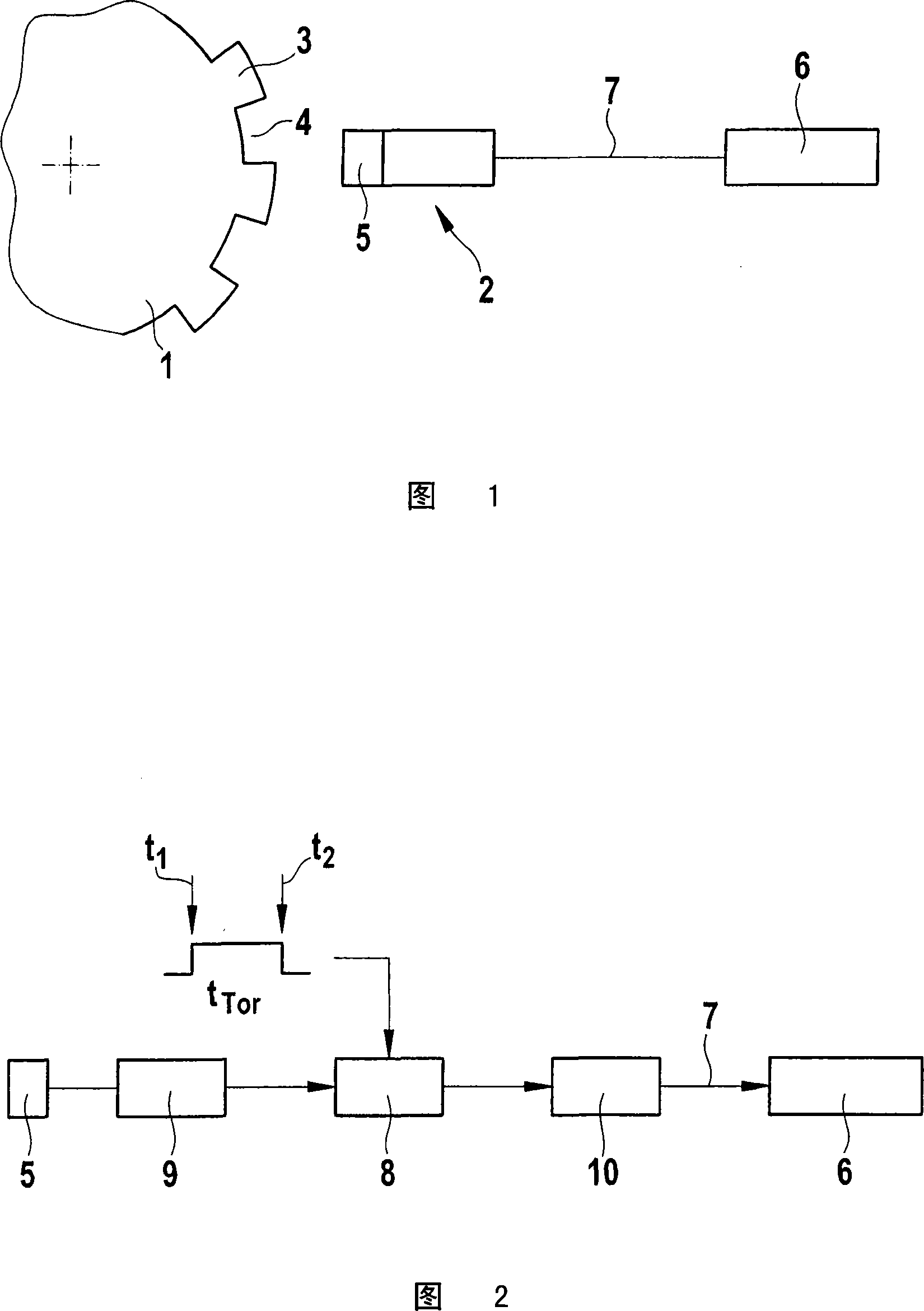
[0014] Figure 1 shows the arrangement of a sensor wheel 1 and a sensor 2. The sensor wheel 1 is connected to an unshown crankshaft of an internal combustion engine, so that the sensor wheel 1 and the crankshaft rotate together. The sensor shaft 1 includes marks, for example marks in the form of teeth 3 and tooth slots 4 arranged alternately. When these marks pass by the sensor 2, these marks cause an electrical signal of the sensing element 5. The sensing element 5 may be, for example, a Hall-sensor, an inductive sensor or the like. In this way, the electrical signal of the sensing element 5 is a rectangular voltage. This rectangular voltage corresponds to the sequential expansion of the teeth 3 and the cogging 4 of the sensor wheel 1. The tooth 3 and the tooth slot 4 produce two different states in the sensor 2. These states are transmitted to an electronic controller 6 at two levels of voltage (rectangular voltage) or current, for example, as a series of pulses. Data is transmit...


PUM


Abstract

Method for determining the speed of rotation of a rotating shaft, assigning to the shaft a device (1) having markings (3, 4) which, when passing by a sensing element (5) of a sensor (2) An electrical signal is generated, wherein the sensor (2) includes an evaluation device (8, 9) which counts the number of times a marker passes by the sensing element (5) within a gate time (tTor) and uses this as a value (zist) to a controller (6). The gate time (tTor) is derived in a time increment, and a pulse with an actual duration (tSynist) derived from the time increment is transmitted to the controller (6), and passed through the controller (6) and A setpoint duration (tSynsoll) is compared, the value (Zist) being corrected by the correction value (K) determined from the comparison of the actual duration (tSynist) and the setpoint duration (tSynsoll).

Description

Technical field [0001] The present invention relates to a method and a system for measuring the speed of a rotating shaft. The shaft is provided with a device having markings which generate an electrical signal when passing by a sensing element of a sensor, wherein The sensor includes an analysis device that counts the number of markers passing by the sensor element within a gate time (Torzeit) and transmits it as a value to a controller. In addition, the present invention also relates to a sensor used in such a system, and a computer program for executing the method. Background technique [0002] In the prior art, the measurement of the rotational speed of a rotating shaft is performed, for example, by measuring a mark of a sensor wheel. These marks pass by a sensor when the shaft rotates and are assigned to the incremental electrical signals of the rotational movement of the shaft. Usually, for example, a device with grooves and tooth grooves is provided in the crankshaft. When...

Claims


Application Information

Patent Timeline
Patent Type & Authority Applications(China)
IPC IPC(8): G01P3/481G06F17/00
CPCG01P3/481G01P3/489
Inventor U·卡斯纳
Owner ROBERT BOSCH GMBH
Why Eureka
Try Eureka