
Duty cycle estimation system and method

a duty cycle and estimation system technology, applied in the field of duty cycle determination and estimation, can solve the problems of high cost of implementation of known battery monitoring circuits, unwound, and other vlu circuitry and software dependent on clocking functions, and achieve the difficulty of designing based on high resolution clocks

Active Publication Date: 2012-07-24
CALAMP WIRELESS NETWORKS
View PDF14 Cites 4 Cited by
  • Summary
  • Abstract
  • Description
  • Claims
  • Application Information

AI Technical Summary

Problems solved by technology

Known battery monitoring circuits are expensive to implement and thus are not desirable.
Also, other VLU circuitry and software dependent on a clocking function would be more difficult to design based on a high resolution clock.
Both measurements, of course, are inaccurate.

Method used


Image

  • Duty cycle estimation system and method
  • Duty cycle estimation system and method
  • Duty cycle estimation system and method

Examples


Embodiment Construction

[0023]Aside from the preferred embodiment or embodiments disclosed below, this invention is capable of other embodiments and of being practiced or being carried out in various ways. Thus, it is to be understood that the invention is not limited in its application to the details of construction and the arrangements of components set forth in the following description or illustrated in the drawings. If only one embodiment is described herein, the claims hereof are not to be limited to that embodiment. Moreover, the claims hereof are not to be read restrictively unless there is clear and convincing evidence manifesting a certain exclusion, restriction, or disclaimer.

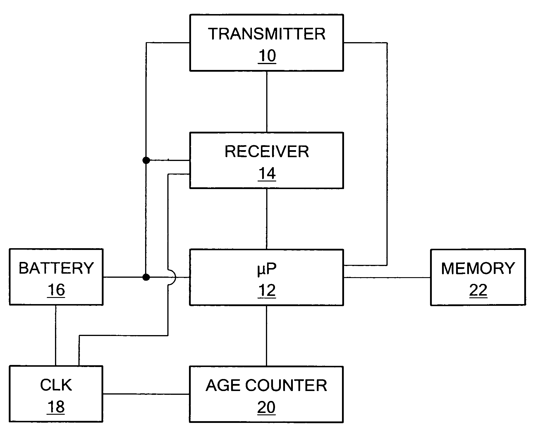
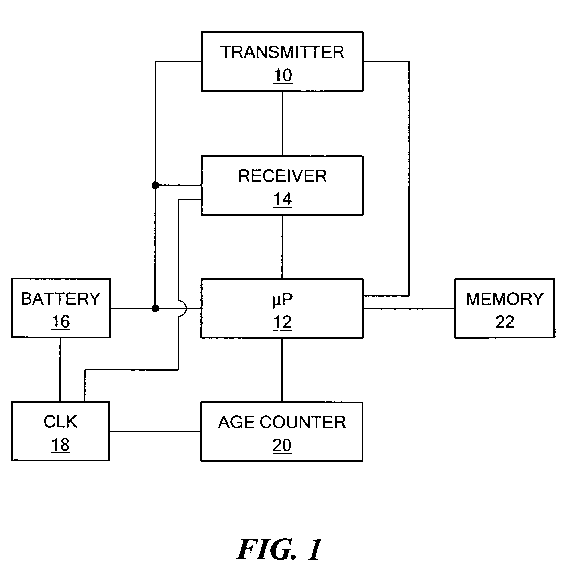
[0024]FIG. 1 shows an example of the primary components associated with a typical vehicle locating unit. Transmitter 10 is activated by processor 12 when receiver 14 receives the appropriate signal. Battery pack 16 serves as either the primary or backup power supply for the various subsystems in the VLU including receiver 1...


PUM


Abstract

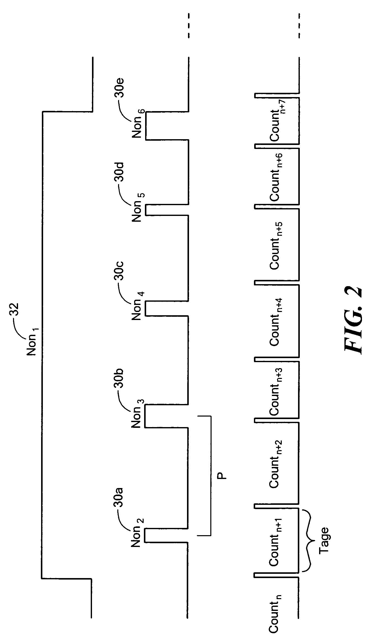
A method of operating a vehicle locating unit wherein an activation signal is received when the vehicle is stolen and in response to the activation signal, a signal indicating the vehicle has been stolen is transmitted. The receiver is energized for an actual duration Non periodically to listen for the activation and other signals. Estimating how long the receiver has been on includes incrementing a counter at a count resolution where Non is typically at least sometimes less than the count resolution. Estimating the total amount of time the receiver was energized is based on a measured on time after it converges with the actual on time.

Description

FIELD OF THE INVENTION[0001]The subject invention relates to duty cycle determinations and estimations.BACKGROUND OF THE INVENTION[0002]The duty cycle of a device is the duration the device is active in some period of time. Determining the duty cycle is important in many systems.[0003]In but one example, the applicant's successful LoJack® system includes a vehicle locating unit (VLU) hidden in a vehicle. See U.S. Pat. Nos. 4,177,466 and 4,818,998 incorporated herein by this reference. The VLU includes a receiver and a transmitter (e.g., a transponder). When the vehicle is reported stolen, an RF signal to that effect is transmitted from a base station via one or more relay towers to the VLU in the stolen vehicle to activate the VLU transmitter. Police cars equipped with a vehicle tracking unit (VTU) can detect and track the signal emitted by the VLU in order to retrieve the stolen vehicle.[0004]The battery providing power to the VLU has a finite capacity and power is consumed, inter ...

Claims


Application Information

Patent Timeline
Patent Type & Authority Patents(United States)
IPC IPC(8): H04B17/00H04B1/40
CPCB60R25/102H04W52/0229G01R31/3679Y02B60/50G01R31/392Y02D30/70
Inventor BOURQUE, STEPHEN
Owner CALAMP WIRELESS NETWORKS
Learn More