Cage rotor for an asynchronous motor

A technology for asynchronous motors and cage rotors, applied in the direction of asynchronous induction motors, electrical components, electromechanical devices, etc., can solve the problems of reduced risk of fracture, fracture, and existence, and achieve the effects of reducing inertia moment and saving materials

Active Publication Date: 2008-07-02
SIEMENS AG
View PDF2 Cites 9 Cited by
  • Summary
  • Abstract
  • Description
  • Claims
  • Application Information

AI Technical Summary

Problems solved by technology

[0005] The disadvantage is that the risk of fracture of the connection between the rotor bar and the short-circuit ring is reduced, but the possibility of fracture still exists

Method used


Image

  • Cage rotor for an asynchronous motor
  • Cage rotor for an asynchronous motor
  • Cage rotor for an asynchronous motor

Examples


Embodiment Construction

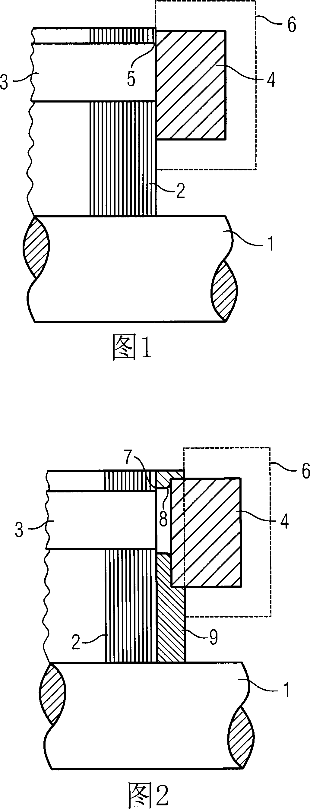
[0032] Figure 1 shows a partial view of a cage rotor in the prior art. In rotary electric machines working on the principle of induction, the short-circuit winding in the rotor is made of a material with good electrical conductivity, in particular copper or aluminium. On the one hand, this short-circuit winding is formed by a number of rotor bars 3 with a defined cross section, which are embedded in the rotor lamination stack 2 . On the other hand, a short-circuit ring 4 is respectively arranged on the end faces of the laminated core, which short-circuit ring connects all the rotor bars 3 on the respective rotor side to one another, ie electrically shorts these rotor bars. Currently, rotor windings are generally produced from aluminum by die-casting.

[0033] As shown in FIG. 1, during casting, the lamination stack 2 is located between two die-casting molds 6 arranged on its end faces, thereby forming a cavity formed by the rotor bar 3 and the short-circuit ring 4 in the lami...


PUM


Abstract

The invention relates to an asynchronous machine with a stator or a cage rotor, wherein the cage rotor has a shaft (1) and a lamination stack (2) in which a plurality of rotor bars ( 3), the rotor bars are respectively inserted into the openings (10) of an end plate (9) at both ends of the lamination stack (2), and closed with a short-circuit ring (4), and the short-circuit ring makes all The ends of the rotor bars (3) on the cage rotor side are electrically conductively connected, wherein each end plate (9) has an annular protrusion which at least partially covers the short circuit in a form-fitting manner Outside the rings (4), each end plate (9) contains a part of the rotor bar (3) and a part of the shorting ring (4).

Description

technical field [0001] The invention relates to an asynchronous machine with a stator and a cage rotor, wherein the cage rotor has a shaft and a lamination stack in which a plurality of rotor bars are arranged, the rotor bars being arranged in a lamination Both ends of the group are each inserted into openings in an end plate and closed with short-circuit rings which electrically connect the ends of the rotor bars on one side of the cage rotor. Background technique [0002] Electric motors are used in many technical fields. Motors are divided into DC motors, AC motors and three-phase motors. Three-phase motors can be further divided into three-phase synchronous motors and three-phase asynchronous motors. [0003] All of these motors consist of a stationary stator and a rotatably mounted rotor. Depending on the specific design, the rotor is equipped with a winding system. This winding system can consist of one or more wire wound windings or strip windings. Cage windings ...

Claims


Application Information

Patent Timeline
Patent Type & Authority Applications(China)
IPC IPC(8): H02K17/16
CPCH02K17/16
Inventor 丹尼尔·弗霍文
Owner SIEMENS AG
Why Eureka
Try Eureka