Disk unit

An optical disc device and optical disc technology, which are applied in the directions of recording information storage, instruments, etc., can solve the problem of inability to take out small-diameter optical discs.

Inactive Publication Date: 2011-01-19
TEAC CORP
View PDF2 Cites 0 Cited by
  • Summary
  • Abstract
  • Description
  • Claims
  • Application Information

AI Technical Summary

Problems solved by technology

In addition, the entire small-diameter optical disk enters the inner side of the optical disk device from the insertion port, and the operator cannot take out the small-diameter optical disk.
Then, in the conventional chuck-type optical disk device, there is a problem that the wrong insertion of an optical disk different from the predetermined size becomes the cause of failure of the optical disk device.

Method used


Image

  • Disk unit
  • Disk unit
  • Disk unit

Examples


Embodiment 1

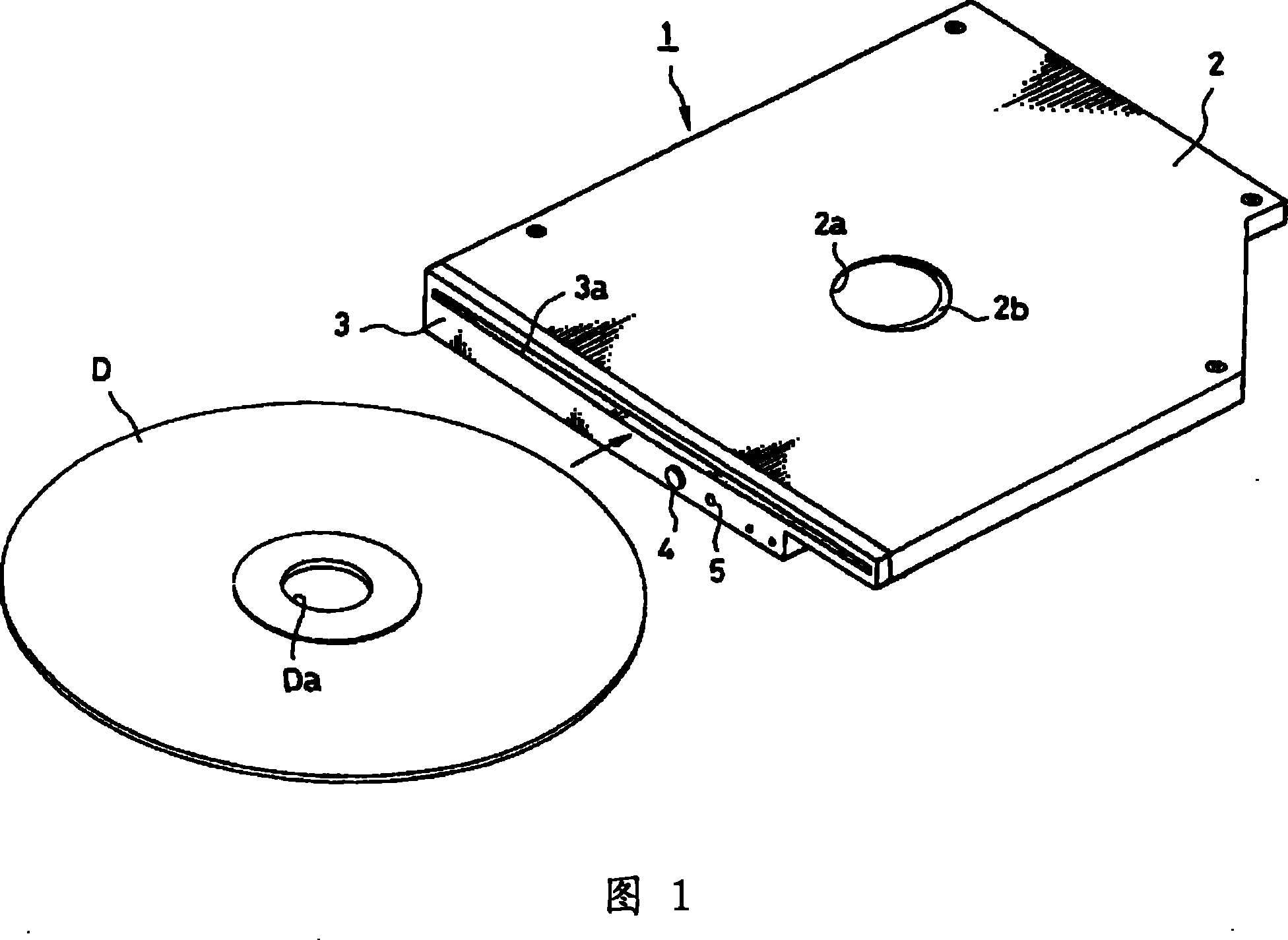
[0154] figure 1An external view showing a chuck type optical disc device 1 embodying the present invention, an opening 2a is formed in the center of the top plate of the casing 2 constituting an isolated state, and a convex portion 2b protruding inward is formed at the opening peripheral portion of the opening 2a. A front cover 3 is fixed at the front end of the casing 2, and the front cover 3 is provided with an insertion port 3a for inserting an optical disc D (the first disc-shaped recording medium) with a prescribed outer diameter (specifically, a diameter of 12 cm); The button 4 is used to instruct to unload the optical disk D stored inside the device and the indicator 5 is used to display the operation state of the optical disk device 1 .

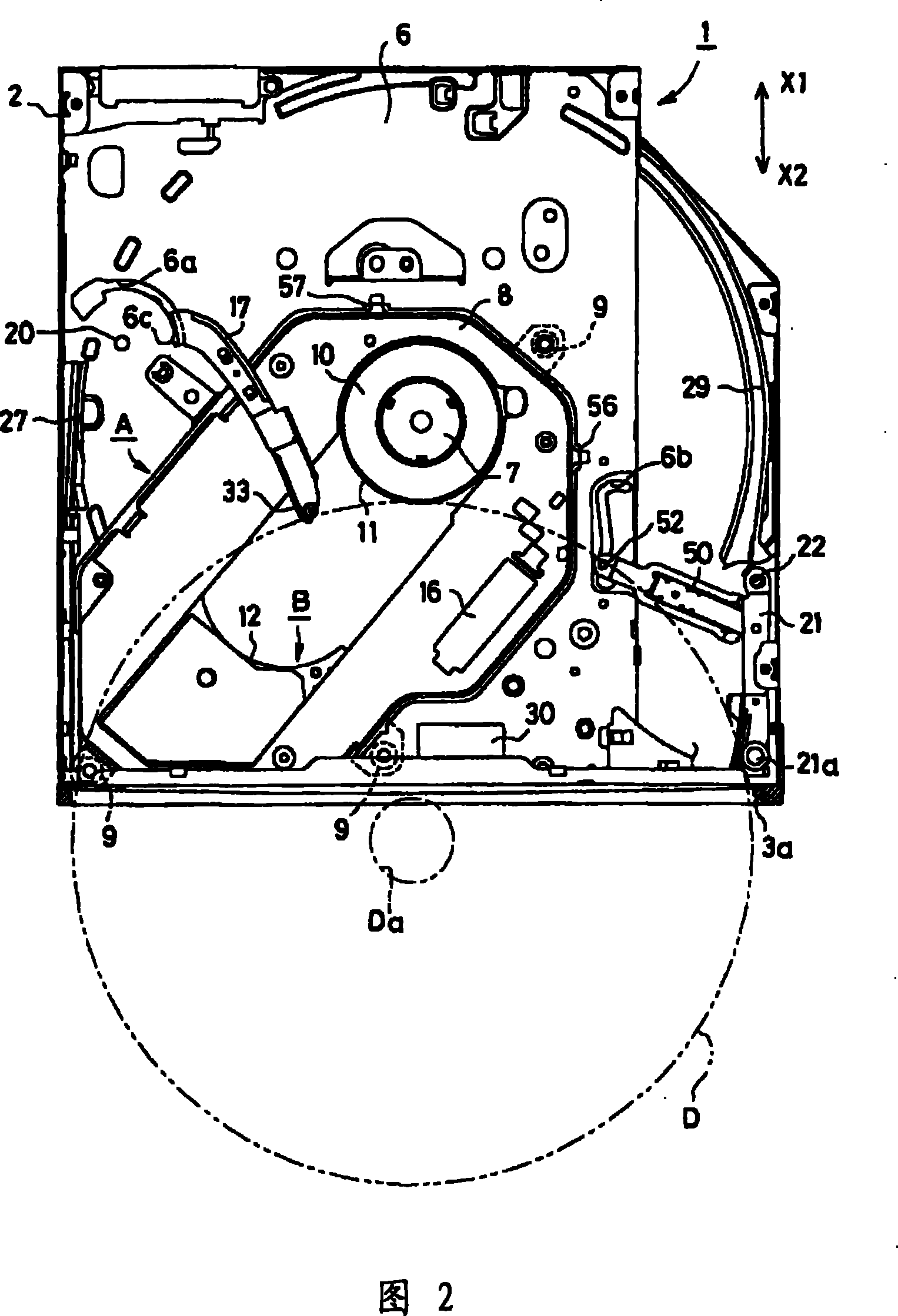
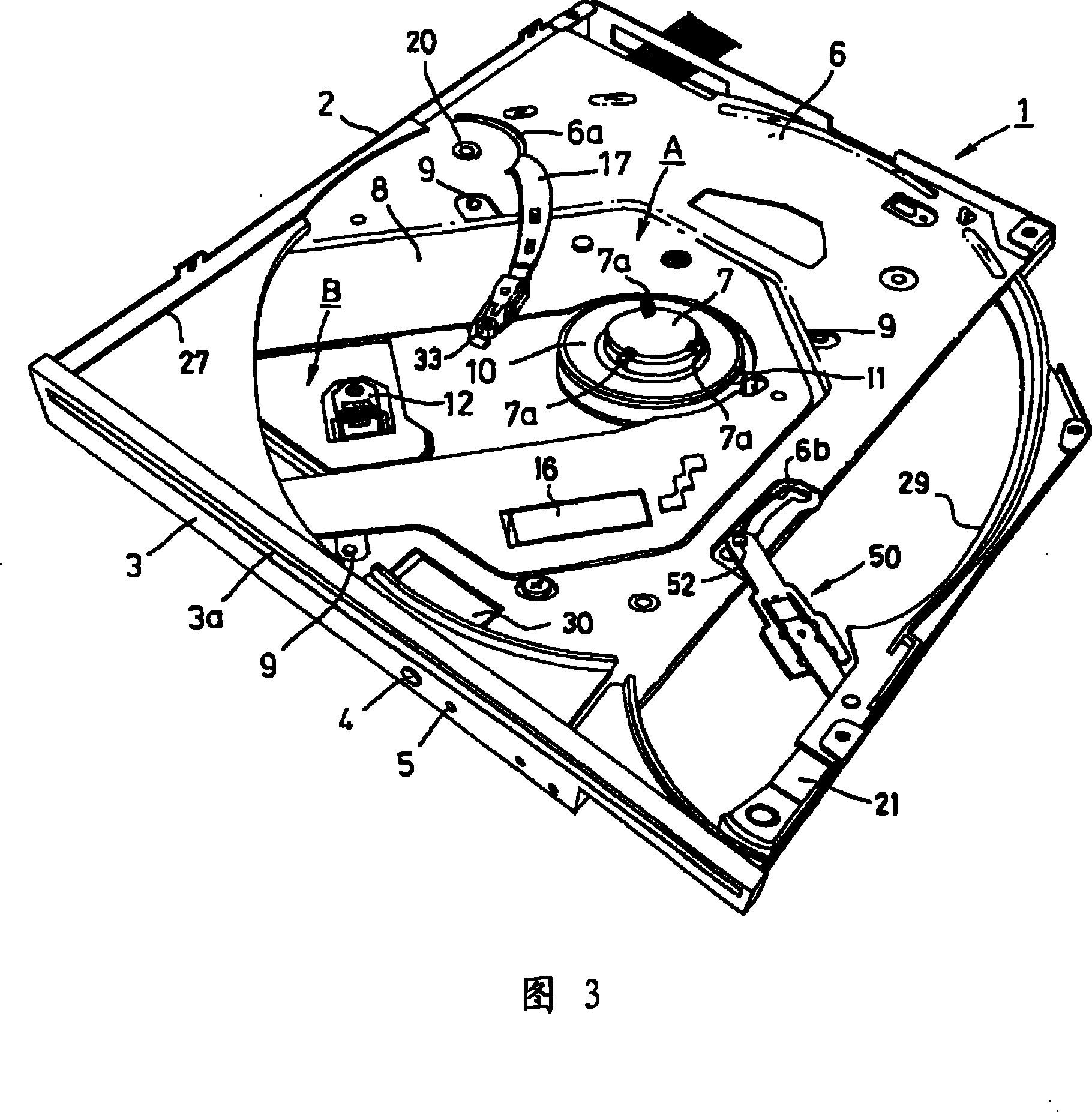
[0155] figure 2 It is a plan view of the state where the top plate portion of the casing 2 of the optical disc device 1 is removed, image 3 is its stereogram. A bottom plate 6 is arranged inside the casing 2, and a recording / pla...

Embodiment 2

[0191] Next, Embodiment 2 of the present invention will be described below. Figure 19It is a plan view of the optical disk drive 1 in a state where the top plate portion of the casing 2 is removed. exist Figure 19 , symbol 17 is in charge of guiding to the inside of the device and the action of pushing out the disc D with a diameter of 12 cm to the outside of the device. A stopper 19 is installed at its front end. The case of the 8cm disc Ds is used to prevent wrong insertion and prevent access to the inside of the device. In addition, since the drive mechanism for swinging the disc support arm 17 is the same as the arm drive mechanism C used in the first embodiment, its description is omitted.

[0192] The stopper 19 as Figure 20 As shown, the abutting portion 19a contacting the front peripheral edge of the 8 cm optical disc Ds is attached to the front end of the optical disc holding arm 17 via the elastic portion 19b. More specifically, after the locking portion 19c o...


PUM

PropertyMeasurementUnit
diameteraaaaaaaaaa

Abstract

To provide a disk unit of a slot-in system exclusive for a 12 cm disk, which is prevented from getting out of order by blocking penetration of a 8 cm disk into the disk unit. At a state that a disk support arm 17 is on standby for the carry-in of the 12 cm disk D, when the 8 cm disk Ds is inserted and the penetration into the unit can not be blocked by a holder 18 of the disk support arm 17, the penetration of the 8 cm disk Ds into the unit is blocked by the abutment of a front rim of the 8 cm disk Ds against an abutting part 19a of a stopper 19 mounted at the distal end of the disk support arm 17.

Description

[0001] The present invention is a divisional application of the Chinese invention patent application (application number: 200510051963.5, application date: February 23, 2005, invention name: optical disk device). technical field [0002] The present invention relates to an optical disc device for driving an optical disc (such as CD-R / RW, DVD-R / -RW / RAM / +R / +RW, etc.) as a recording medium for recording a large amount of data in various computer systems and other data devices , particularly relates to a mechanism for preventing misinsertion of discs with different diameters. Background technique [0003] Generally, an optical disc device installed in a personal computer or the like has an optical disc tray for loading an optical disc, and the optical disc tray is moved forward and backward. On the other hand, the optical disc loaded in the optical disc tray is driven in the main body of the optical disc device to record or play data. [0004] On the other hand, a so-called slo...

Claims


Application Information

Patent Timeline
Patent Type & Authority Patents(China)
IPC IPC(8): G11B17/04G11B17/051
Inventor 藤泽辰一佐藤琢
Owner TEAC CORP
Why Eureka
Try Eureka