

Air conditioner
A technology for air conditioners and liquid accumulators, which is applied in the directions of compressors with reversible cycles, lighting and heating equipment, refrigeration components, etc., can solve problems such as increased production costs and increased volume.
- Summary
- Abstract
- Description
- Claims
- Application Information
AI Technical Summary
Problems solved by technology
Method used
Image

Examples
no. 1 example
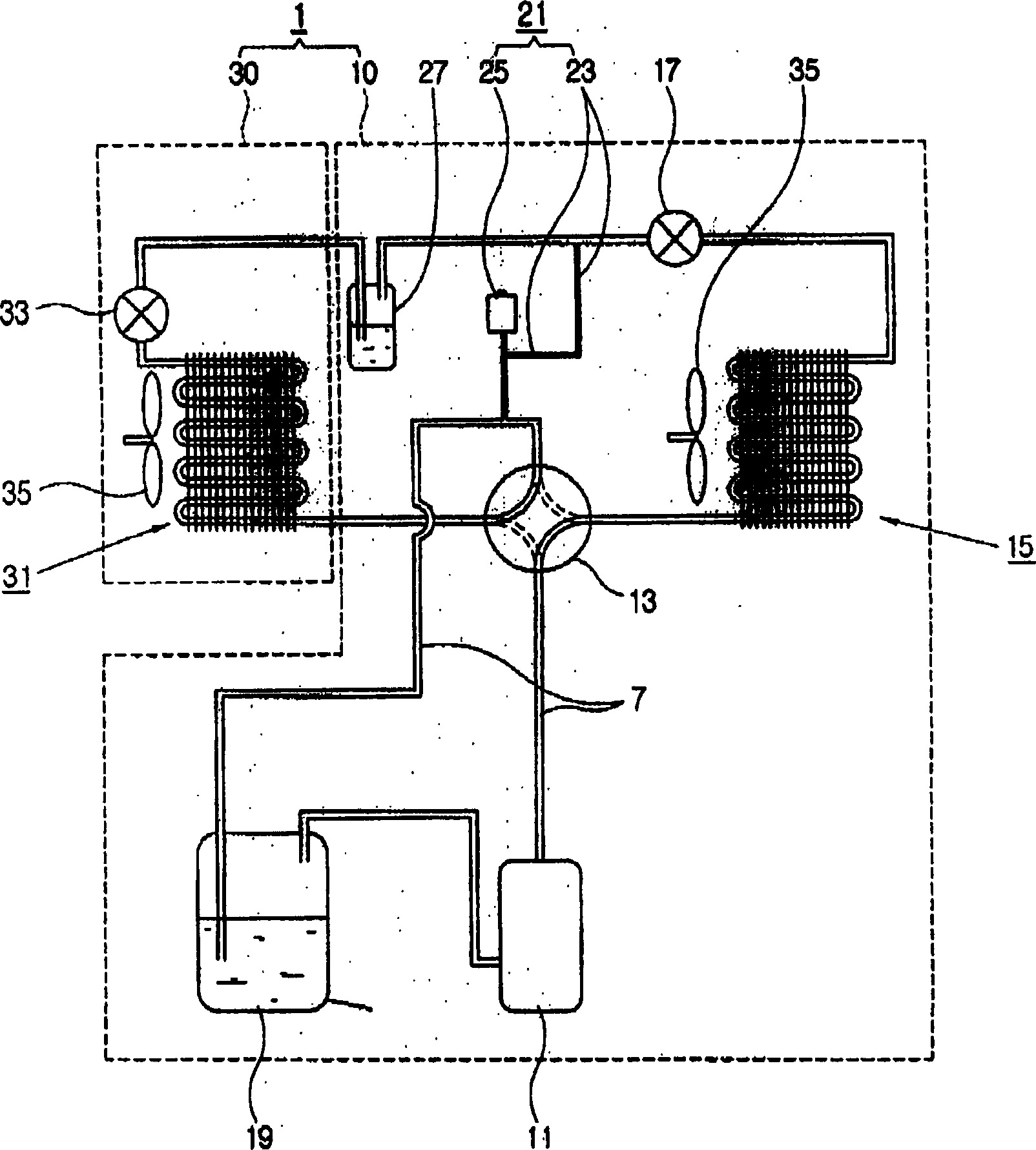
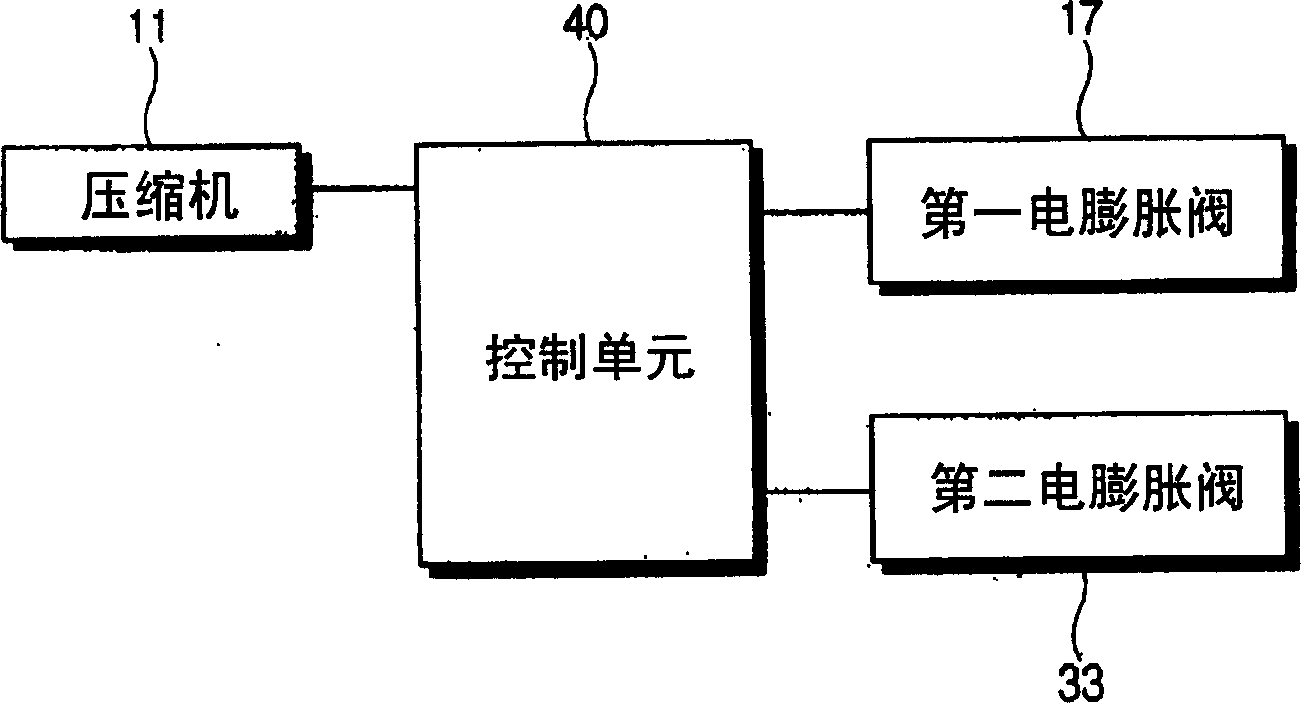
[0026] Such as figure 1 and 2 As shown, the air conditioner according to the first embodiment of the present invention includes a freezing device 1 configured to control the temperature of indoor air, and a control unit 40 for controlling the freezing device 1 .
[0027] The refrigeration device 1 includes: a compressor 11; a plurality of heat exchangers 15, 31 for exchanging heat with the refrigerant supplied by the compressor 11; a plurality of electric expansion valves arranged between the plurality of heat exchangers 15, 31 17, 33; and an accumulator 19 disposed between the heat exchangers 15, 31 and the compressor 11. The freezing device 1 forms a closed circuit through the refrigerant pipe 7 so that the refrigerant can circulate among the compressor 15 , the plurality of heat exchangers 11 and 31 , and the accumulator 19 . The freezing device 1 further includes a pressure control unit 21 configured to control the pressure of refrigerant accommodated between the plurali...
no. 2 example
[0047] Figure 4 is a schematic view of an air conditioner according to a second embodiment of the present invention. As shown in the figure, the refrigerating device 101 of the air conditioner according to the second embodiment is different from the first embodiment, wherein the refrigerating device 101 further includes a check valve 50 disposed in the refrigerant outlet area of the compressor 11 , used to prevent the refrigerant from flowing back into the compressor 11.
[0048] Such as Figure 4 As shown, the check valve 50 is disposed between the compressor 11 and the four-way valve 13 , and can prevent the refrigerant from flowing back from the first heat exchanger 15 or the second heat exchanger 31 to the compressor 11 .
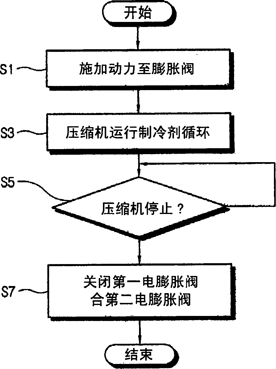
[0049] In the case where the check valve 50 is set, the control unit 40 may close one of the first and second electric expansion valves 17, 33 when the operation of the compressor 11 is stopped. During the air cooling operation of the refrigeratin...
no. 3 example
[0053] Figure 5 is a schematic view of an air conditioner according to a third embodiment of the present invention. As shown, the air conditioner according to the third embodiment includes a freezing device 201 configured to control the temperature of indoor air, etc., and a control unit (not shown) that controls the freezing device 201 .
[0054] The refrigerating device 201 includes a compressor 11, a plurality of heat exchangers 15, 31 for exchanging heat with refrigerant supplied from the compressor 11, an electric expansion valve 217 provided between the plurality of heat exchangers 15 and 31, and a An accumulator 19 between the exchangers 15, 31 and the compressor 11, and a check valve 50 arranged in the refrigerant outlet area of the compressor 11 for preventing the refrigerant from flowing back into the compressor. The freezing device 201 may further include a four-way valve 13 configured to change the flow direction of the refrigerant in the plurality of heat exch...
PUM
 Abstract
Description
Claims
Application Information