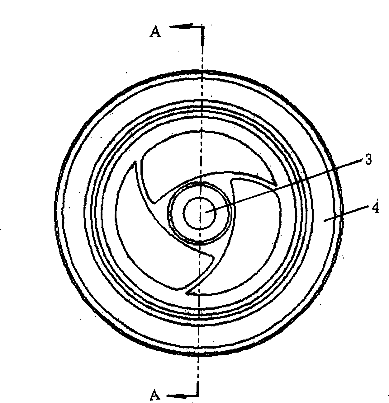
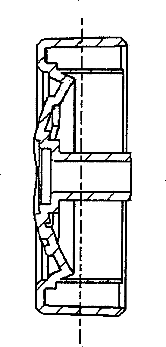
Idler wheel structure of dust collector
A technology of roller structure and vacuum cleaner, applied in vacuum cleaners, cleaning equipment, household appliances, etc., can solve the problem of oil loss and achieve the effect of preventing noise
- Summary
- Abstract
- Description
- Claims
- Application Information
AI Technical Summary
Problems solved by technology
Method used
Image

Examples
Embodiment Construction
[0026] The present invention will be described in detail below with reference to the drawings and examples.
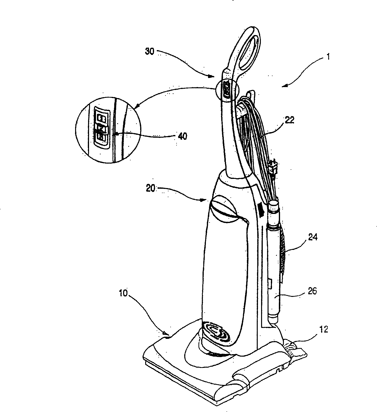
[0027] The roller structure of vacuum cleaner of the present invention, as figure 1 as shown,
[0028] The upright vacuum cleaner 1 is roughly divided into the following parts: the vacuum cleaner includes: a suction pipe body 10 supporting the vacuum cleaner 1, a casing 20 connected to the suction pipe body 10 and vertically upright; a handle 30 is formed on the upper part of the casing 20; the handle 30 Formed integrally with the casing 20 . A switch assembly 40 for controlling the operation of the vacuum cleaner 1 is formed on one side of the handle 30; a power cord 22 for supplying power to the fan motor is formed on one side of the housing 20; the power cord 22 should be made elongated. A suction hose 24 is formed on the rear side of the casing 20 . A connection pipe 26 is attached to a side surface of the casing 20 .
[0029] Such as figure 1 As shown, a roll...
PUM
 Abstract
Description
Claims
Application Information
 - R&D Engineer
- R&D Manager
- IP Professional
- Industry Leading Data Capabilities
- Powerful AI technology
- Patent DNA Extraction
Browse by: Latest US Patents, China's latest patents, Technical Efficacy Thesaurus, Application Domain, Technology Topic.
© 2024 PatSnap. All rights reserved.Legal|Privacy policy|Modern Slavery Act Transparency Statement|Sitemap