Upper and lower path switching device for traveling body for transportation

A technology of channel switching and moving bodies, which is applied in the direction of lifting devices, transportation and packaging, conveyors, etc., can solve problems such as disengagement and increase in overall equipment costs, and achieve improved safety, reduced load resistance performance, and improved positioning strength. Effect

Active Publication Date: 2008-07-30
DAIFUKU CO LTD
View PDF1 Cites 15 Cited by
  • Summary
  • Abstract
  • Description
  • Claims
  • Application Information

AI Technical Summary

Problems solved by technology

In such a past configuration, not only is the supporting member required to have a very large load resistance performance, even after being supported by the supporting member, the lifting drive mechanism that lifts the lifting body still operates for a certain period of time. In the conventional sling-type lifting drive mechanism, after the lifting body is supported by the supporting member, the sling is slack. As a result, measures must be taken to prevent the sling from being detached from the guide wheels, etc., resulting in an increase in the cost of the overall equipment.

Method used


Image

  • Upper and lower path switching device for traveling body for transportation
  • Upper and lower path switching device for traveling body for transportation
  • Upper and lower path switching device for traveling body for transportation

Examples


Embodiment Construction

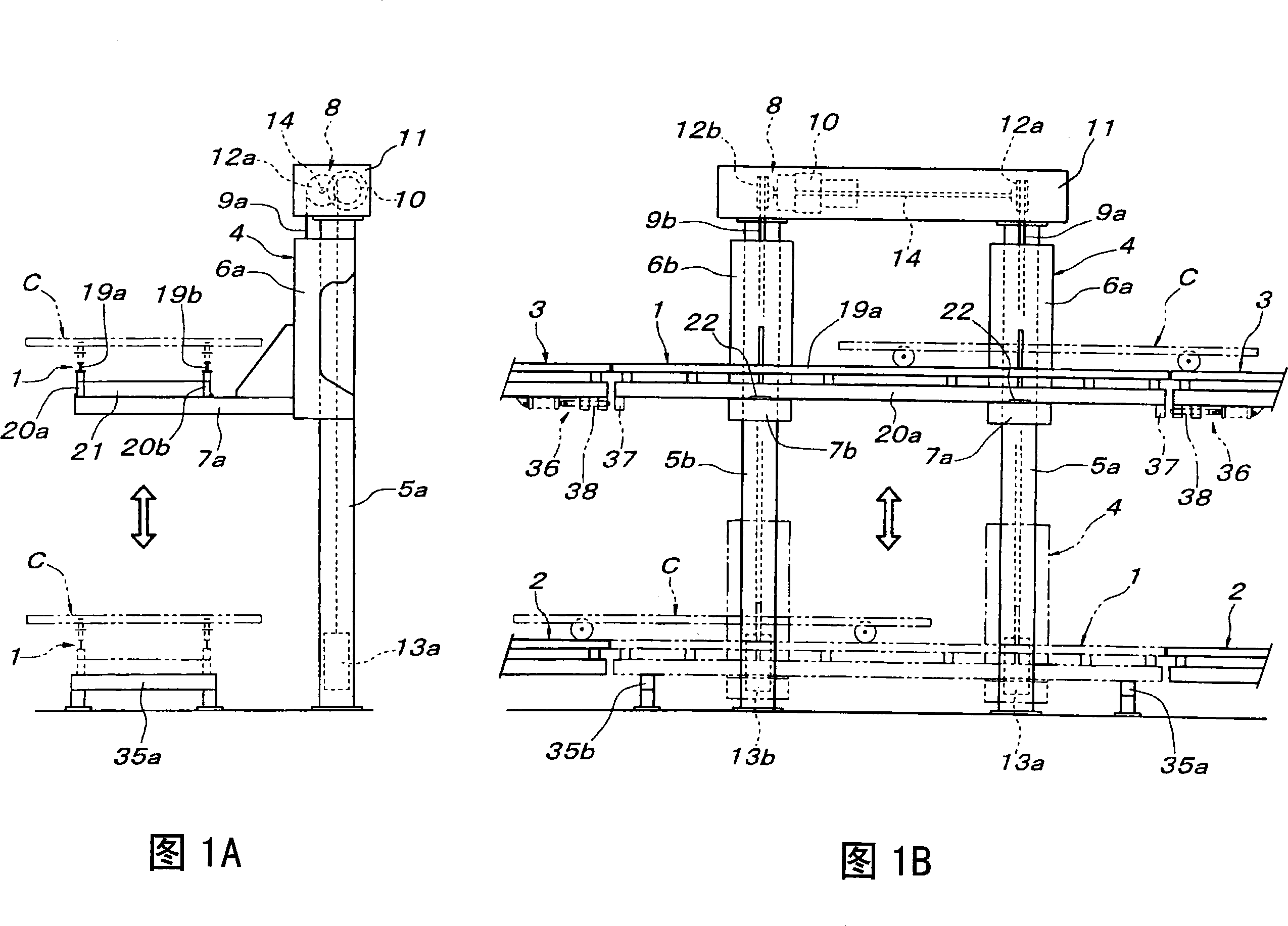
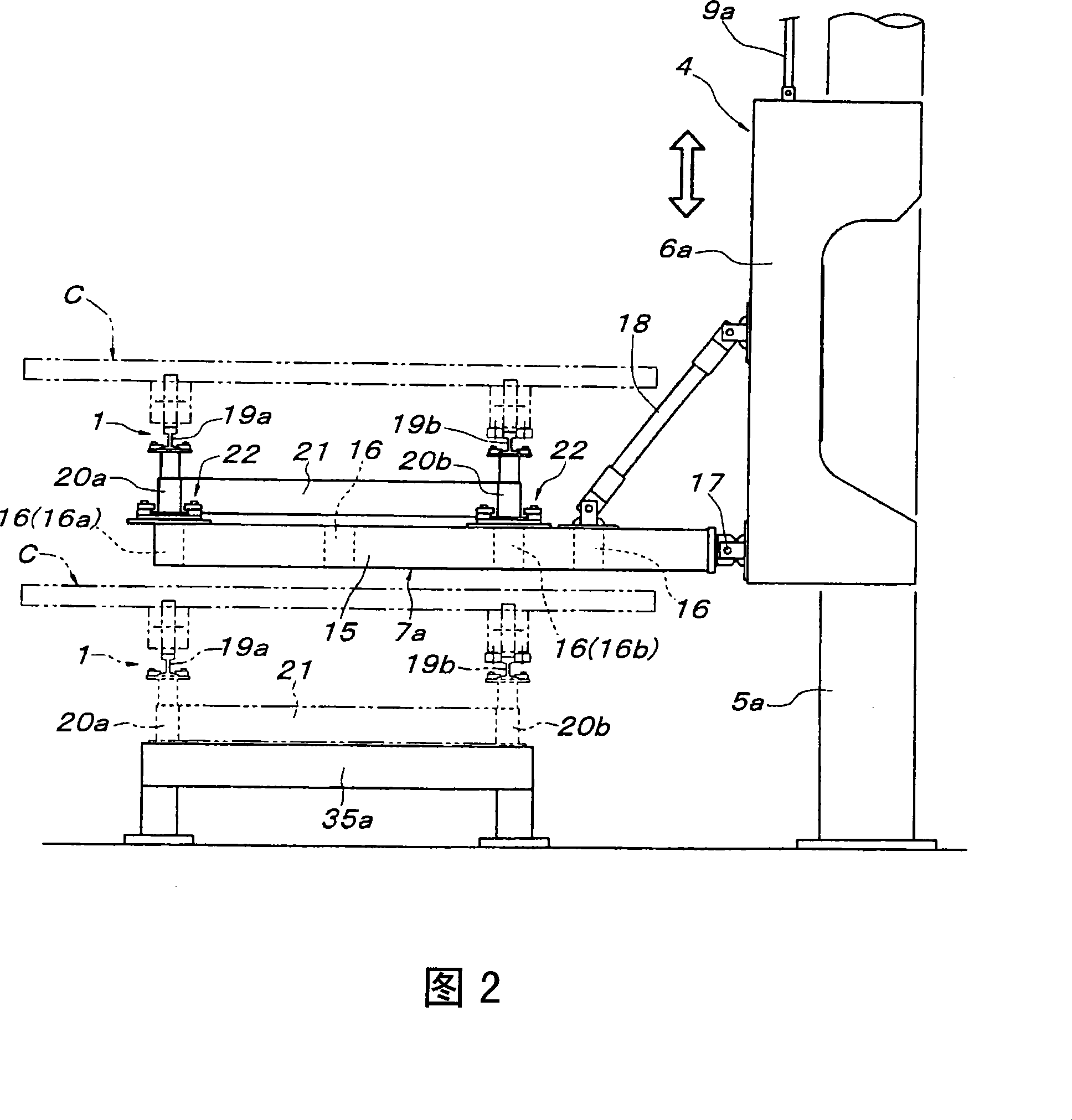
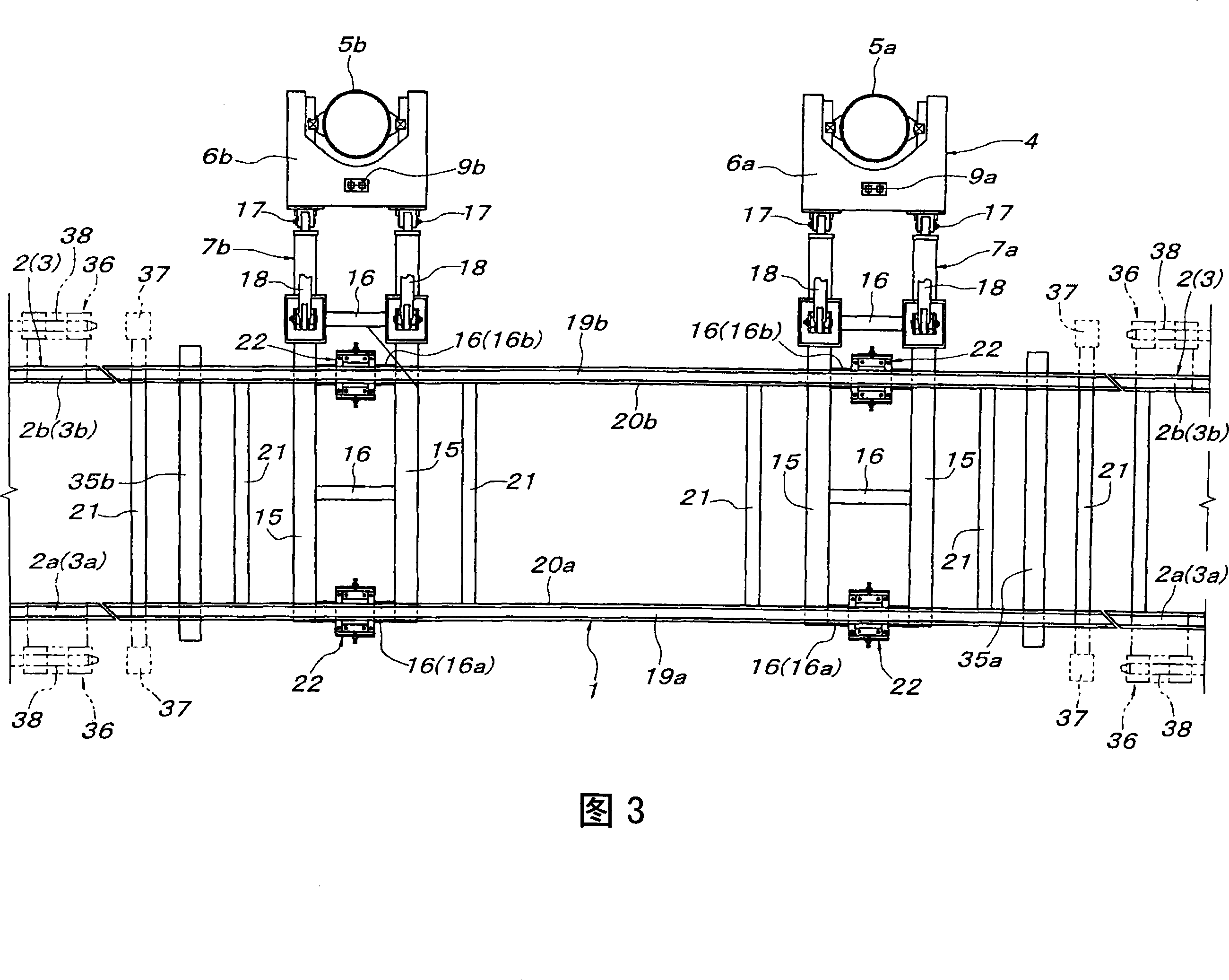
[0020] Below according to accompanying drawing, specific embodiment of the present invention is described, and in Fig. 1, label 1 represents lifting guide rail, and label 2 represents the front and rear sides near the bottom end of the lifting passage of lifting guide rail 1, lays on the floor. Bottom side fixed guide rails, reference number 3 represents the top side fixed guide rails erected on the front and rear sides of the lifting passage near the top of the lifting guide rail 1 . Reference number 4 represents the lifting body supporting the lifting guide rail 1 to realize the lifting, which is composed of a pair of lifting main bodies 6a, 6b and a pair of horizontal arm parts 7a, 7b, and the pair of lifting main bodies 6a, 6b are vertically arranged on the lifting guide rail along the side by side. A pair of pillars 5a, 5b on one side of the lifting passage of 1 are lifted, and the pair of horizontal arm parts 7a, 7b extend from the pair of lifting main bodies 6a, 6b to th...


PUM


Abstract

The present invention easily improves the accuracy of connection level alignment between an elevating guide rail and a fixed side guide rail in a path switching device which switches vertically a traveling path of a conveyance carriage or the like via an elevating guide rail, and in an upper and lower path switching device for a traveling body for transportation, including an elevating guide rail supported horizontally by an elevating body, upper fixed guide rails to be connected to the elevating guide rail at a lifted position of the elevating body, and lower fixed guide rails which are connected to the elevating guide rail at a lowered position of the elevating body, the elevating guide rail is supported movably vertically in a predetermined range with respect to the elevating body, and receiving members for receiving the elevating guide rail at a level at which the elevating guide rail is connected to the lower fixed guide rails before the elevating body reaches a lower limit thereof are provided.

Description

technical field [0001] The present invention relates to an up-and-down path switching device for transferring a transport moving body such as a transport trolley from one of a top fixed guide rail and a bottom fixed guide rail to the other via an elevating guide rail. Background technique [0002] Through Japanese Patent Application Laid-Open No. 4-350017 etc. (hereinafter referred to as known documents), it is known that there is such an upper and lower path switching device for the mobile body for transportation, but in order to safely and smoothly perform the switching between the lifting guide rail and the upper and lower fixed guide rails In the transfer of the moving body for transportation, it is necessary to stop the raised and lowered rails at positions connected to the upper and lower fixed rails at the same elevation with good accuracy. That is, the control system of the elevating drive mechanism of the elevating body supporting the elevating guide rail is require...

Claims


Application Information

Patent Timeline
Patent Type & Authority Applications(China)
IPC IPC(8): B65G47/52B65G37/00B65G35/00B61B13/00B66F1/00B66F7/00
CPCB66F9/02B65G35/08B65G47/57B66F7/02
Inventor 清水芳雄锅田光昭
Owner DAIFUKU CO LTD
Why Eureka
Try Eureka