Pallet stretching-out device for refrigerator

A technology for pulling out devices and trays, which can be used in household refrigeration devices, applications, household appliances, etc., and can solve problems such as access interference, and achieve the effect of preventing interference and making access easier

Active Publication Date: 2008-07-30
TAIZHOU LG ELECTRONICS REFRIGERATOR CO LTD
0 Cites 13 Cited by

AI-Extracted Technical Summary

Problems solved by technology

Therefore, the entry and exit of the above-mentioned hanging basket 27 may be dist...

Method used

[0073] In the storage space of the refrigerator, the first and second trays can be inserted and withdrawn at one time. Therefore, the above-mentioned first...

Abstract

The invention relates to a tray pulling off device used for a refrigerator, which comprises a first tray which is fixed inside a door selectively opening and closing a storage space, and is positioned in the storage space through the drawer in-out manner and has a holding space of an upper opening, a second tray which can be moveably arranged in the in-out direction toward the first tray and has the holding space of the upper opening, a guide component which forms an insertion groove for inserting the upper end of the two lateral sides of the first tray and is used for guiding motion of the second tray, and a connection component which passes through one of the first tray and the guide component and is connected with the rest one, wherein, the insertion groove is formed at an insertion rib which extends downward from the bottom two ends of the guide component.

Application Domain

Technology Topic

Image

  • Pallet stretching-out device for refrigerator
  • Pallet stretching-out device for refrigerator
  • Pallet stretching-out device for refrigerator

Examples

  • Experimental program(1)

Example Embodiment

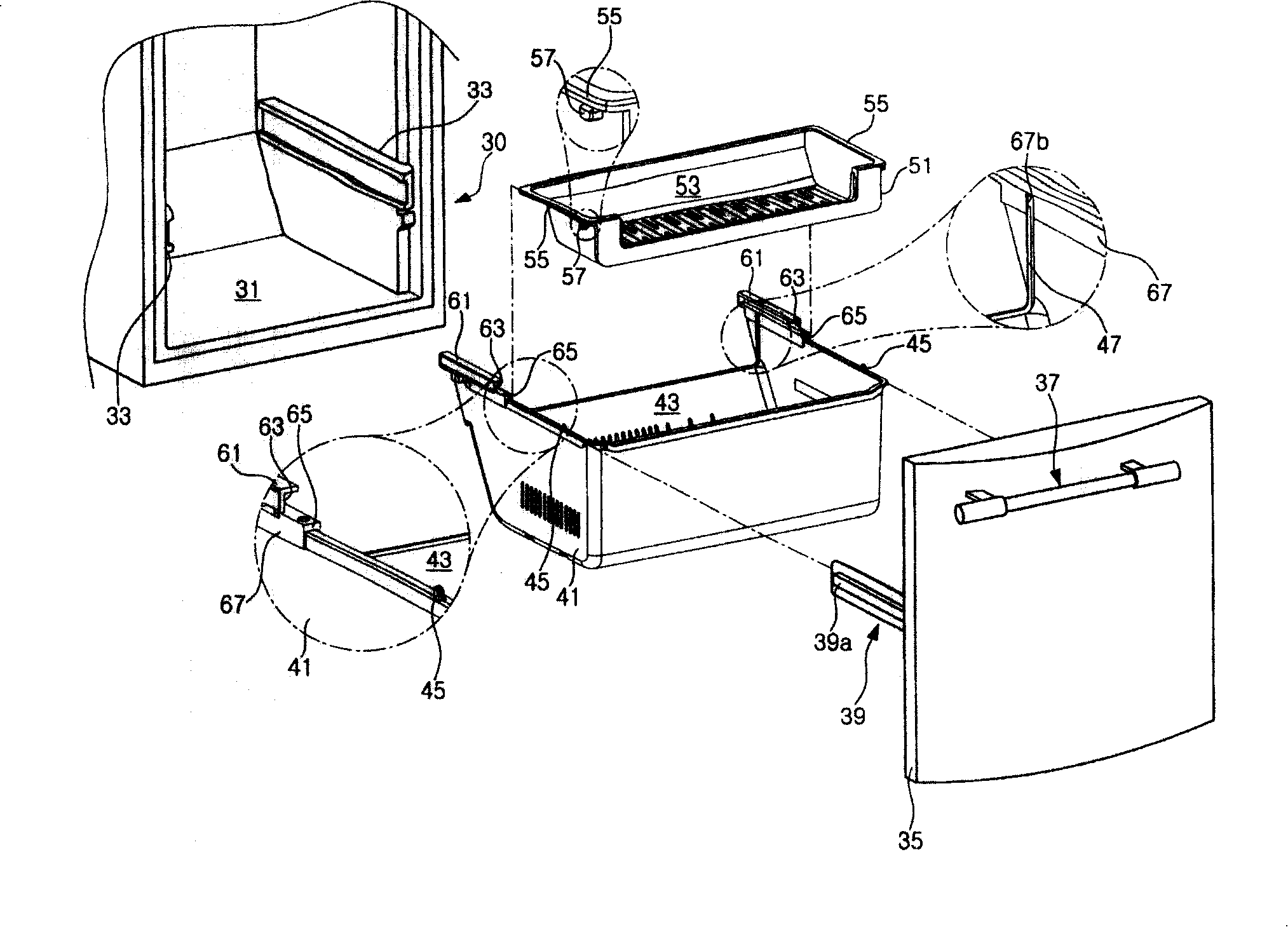
[0040] Such as figure 2 , 3 As shown, the two sides of the storage space 31 of the refrigerator body 30 are provided with guide rails 33. The guide rail 33 is used to guide the entry and exit of the first tray 41, and the first tray 41 will be described below. The guide rail 33 is formed to be long in the in and out direction of the first tray 41, that is, to be long in the front-rear direction of the storage space 31.
[0041] In addition, the present invention is provided with a door 35 for selectively opening and closing the storage space 31. A door handle 37 for the user to hold is provided on the upper front end of the door 35. A guide frame 39 is provided on the inside of the door 35, and the role of the guide frame 39 is to allow the first tray 41 to enter and exit in a drawer in and out manner. The first tray will be described below.
[0042] The guide frame 39 is composed of the following parts: a fixing part (not shown in the figure) fixed to the inside of the door 35; and a pair of connecting parts 39a extending vertically from both ends of the fixing part to the rear. In fact, the connecting portion 39a slides along the guide rail 33, and the inner side surfaces of the connecting portion are in close contact with the outer sides of both side surfaces of the first tray 41, respectively.
[0043] In addition, the first tray 41 is fixed to the inside of the door 35. In order to store food, the first tray 41 has a predetermined storage space 43 with an open upper surface. In addition, hook protrusions 45 are respectively provided at the front ends of the upper ends of both sides of the first tray 41. Such as image 3 As shown, a connecting hole 46 is formed at approximately the center of the upper ends of both sides of the first tray 41.
[0044] The hook protrusion 45 protrudes upward by a certain height from the ends of both sides of the first tray 41, and the hook protrusion 45 prevents the second tray 51 from moving in the pulling direction of the first tray 41 by a certain distance or more. . The second tray 51 will be described below. A connecting member S is connected to the connecting hole 46, and the connecting member S is used to fix the guide member to the first tray 41. The guide part will be described below.
[0045]In addition, the rear end of the first tray 41 and the inner sides of both side surfaces of the first tray 41 corresponding to the connection hole 46 are respectively provided with insertion protrusions 47. The insertion protrusion 47 protrudes from the inner sides of both side surfaces of the first tray 41 to a certain thickness in the directions corresponding to each other, and is formed to be long in the vertical direction. In addition, the insertion protrusion 47 is inserted into the insertion groove 67 b of the guide member 61.
[0046] Such as image 3 As shown, the rear ends of the upper ends on both sides of the first tray 41 are respectively provided with connecting protrusions 48. The above-mentioned connecting protrusion 48 is hung on the connecting hook 69 of the guide member 61 and fixes the guide member 61. The connecting convex portion 48 is formed obliquely and extended downward from the rear end surface of the upper end on both sides of the first tray 41 in the rear direction.
[0047] In addition, a second tray 51 is provided on the upper end of the above-mentioned first tray 41. The second tray 51 is provided to be movable relative to the in-out direction of the first tray 41, that is, to be movable in the forward and backward directions. In order to be able to store food, the second tray 51 has a predetermined storage space 53 with an upper surface and a part of the front surface opened.
[0048] The front and rear length and height of the second tray 51 are smaller than those of the first tray 41. In addition, the width of the second tray 51 corresponds to the width of the first tray 41. In the illustrated embodiment, the shape of the second tray 51 is as follows: a flat hexahedron shape whose front-to-rear length is approximately half of the front-to-rear length of the first tray 41.
[0049] In addition, guide ribs 55 are respectively provided at the upper ends of both sides of the second tray 51, and the guide ribs 55 are formed to be long in the longitudinal direction of the second tray 51. The guide rib 55 extends a certain length outward from the end on both sides of the second tray 51 and is inserted into the guide groove 63 of the guide member 61.
[0050] In addition, a stopper 57 is provided at the front end of the bottom surface of the guide rib 55, and the stopper 57 functions to restrict the range of movement of the second tray 51 with respect to the first tray 41. Wherein, the stopper 57 protrudes downward from the bottom surface of the guide rib 55 by a certain length. If the second tray 51 moves in the pull-out direction of the first tray 41, the stopper 57 is in close contact with the hook protrusion 45; if the second tray 51 moves in the accommodating direction of the first tray 41, the stopper 57 57 is in close contact with the hook base 65 of the guide member 61.
[0051] In addition, guide members 61 are provided on the upper ends of both side surfaces of the first tray 41, and the guide members 61 are formed to be long in the longitudinal direction, and the guide members 61 are used to guide the movement of the second tray 51. The front-rear length of the guide member 61 is smaller than the front-rear length of the second tray 51.
[0052] The guide member 61 will be provided at the rear ends of both side surfaces of the first tray 41 with the position in the longitudinal direction that halves the two side surfaces of the first tray 41 as the center. Therefore, the front end of the guide member 61 is spaced a certain distance from the front end of the upper end on both sides of the first tray 41, and the rear end thereof coincides with the position of the rear end of the upper end on both sides of the first tray 41.
[0053] In addition, each of the guide members 61 is formed with a guide groove 63, and the guide groove 63 is formed to be long in the longitudinal direction. The front surface of the guide groove 63 and the side surfaces corresponding to each other are open, and the guide rib 55 slides while being inserted into the guide groove 63.
[0054] A hook base 65 is provided at the front end of the guide member 61, and the hook base 65 functions to prevent the second tray 51 from moving in the direction in which the first tray 41 is accommodated by a certain distance or more. In the illustrated embodiment, the upper end of the guide member 61 is stepped with respect to the upper ends of both sides of the first tray 41, and the height of the step is equivalent to the thickness of the guide member 61, and the upper end of the guide member 61 is The function is the same as that of the above-mentioned hook station 65.
[0055] In addition, such as image 3 As shown, a through hole 66 is formed on one side of the guide member 61, and the through hole 66 is a portion through which the connecting member S of the connecting hole 46 penetrates. In a state where the guide member 61 is installed on the first tray 41, the through hole 66 is formed at the front end of the guide member 61 corresponding to the connecting hole 46.
[0056] The guide member 61 is provided with insertion ribs 67 at both ends of the bottom surface, respectively. The insertion rib 67 extends downward from both ends of the bottom surface of the guide member 61 by a certain length, and an insertion groove 67 a is formed between the surfaces of the insertion rib 67 corresponding to each other. The width of the insertion groove 67a roughly corresponds to the thickness of the both side surfaces of the first tray 41, and the upper ends of the both sides of the first tray 41 are inserted into the insertion groove 67a.
[0057] In addition, an insertion groove 67b is formed on one side of the insertion rib 67 in close contact with the inner sides of both side surfaces of the first tray 41. The insertion groove 67b is formed by cutting a part of the insertion rib 67 at a certain width, and the insertion protrusion 47 is inserted into the insertion groove 67b.
[0058] Refer to image 3 A connecting hook 69 is provided at the rear end of the bottom surface of the guide member 61 corresponding to the rear end of the insertion groove 67a. In order to be able to catch the connection convex part 48, the said connection hook 69 is formed in the U shape opened upwards as a whole. In more detail, the connecting hook 69 is composed of the following parts: an extension 69a that extends a certain length downward from the rear end of the bottom surface of the guide member 61; and from the front end of the extension 69a to the front, the insertion groove A horizontal portion 69b in which the inside of 67a is horizontally curved; a hook portion 69c that extends upward from the front end of the horizontal portion 69b and actually hooks the connecting convex portion 48.
[0059] Hereinafter, the installation process of the tray pulling-out device for refrigerator of the present invention will be described.
[0060] First, in a state where the guide frame 39 and the first tray 41 are fixed to the back of the door 35, the guide member 61 is installed on the first tray 41 described above. At this time, in a state where the connecting convex portion 48 of the first tray 41 is hung on the connecting hook 69 of the guide member 61, the guide member 61 is rotated about its rear end, so that both sides of the first tray 41 The upper end of the side surface is inserted into the insertion groove 67a of the guide member 61 from the rear end.
[0061] In addition, the insertion convex portion 47 of the first tray 41 is inserted into the insertion groove 67b of the guide member 61 while the ends of both sides of the first tray 41 are inserted into the insertion groove 67a of the guide member 61. Once the ends on both sides of the first tray 41 are completely inserted into the insertion groove 67a, the through hole 66 of the connecting member S that penetrates the first tray 41 is connected to the connecting hole 46 of the guide member 61.
[0062] In this state, in order to install the second tray 51 on the first tray 41, the rear end of the guide rib 55 of the second tray 51 is positioned in front of the opening of the guide groove 63 formed in the guide member 61, And is located in the horizontal position adjacent to it. In order to fully insert the rear end of the guide rib 55 through the front surface of the opening of the guide groove 63, the second tray 51 is moved and the second tray 51 is installed on the first tray 41.
[0063] Below, will refer to Figure 4a and Figure 4b , The use process of the tray pull-out device for refrigerator of the present invention will be described in detail.
[0064] Figure 4a and Figure 4b It is a drawing showing the process of the first and second trays in and out of the preferred embodiment of the tray pulling-out device for refrigerators of the present invention.
[0065] First, the storage space 43 of the first tray 41 and the storage space 53 of the second tray 51 respectively contain food (not shown in the figure). In addition, the first and second trays 41 and 51 will be stored in the storage space 31 of the refrigerator body 30 in the state where food is stored as described above.
[0066] Such as Figure 4a As shown, in a state where the first and second trays 41 and 51 are housed in the storage space 31, the guide rib 55 of the second tray 51 will be completely inserted into the guide groove 63 of the guide member 61. That is, the second tray 51 will be located at the rear end of the first tray 41, and at this time, the stopper 57 of the second tray 51 will be in close contact with the hook base 65 of the guide member 61.
[0067] In addition, in order to take food from the storage space 43 of the first tray 41, the user needs to hold the door handle 37 of the door 35 and pull the door toward the front of the storage space 31. At this time, in order to prevent the first tray 41 from completely detaching from the storage space 31, it is preferable to pull out only the front end portion of the first tray 41.
[0068] As described above, only the front end of the first tray 41 is pulled out to the outside of the storage space 31. Therefore, in such as Figure 4a In the state shown, it is difficult to take food into and out of the storage space 53 of the second tray 51 described above. Therefore, in order to put food into the storage space 53 of the second tray 51, or take out food from the storage space 53, the Figure 4b As shown, the second tray 51 is moved in the pull-out direction of the first tray 41, that is, to the front of the storage space 31.
[0069] When the second tray 51 is moved in the pull-out direction of the first tray 41, the guide rib 55 will slide while being inserted into the guide groove 63. In addition, the stopper 57 moves from a state in close contact with the hook base 65 of the guide member 61 to be in close contact with the hook convex portion 45 of the first tray 41.
[0070] In addition, once the second tray 51 is moved as described above, the user can easily take and place food from the storage space 53 of the second tray 51. As described above, after the food removal or storage operation is completed, the first and second trays 41 and 51 are pulled out to the outside of the storage space 31 in the reverse order of the process. 41 and 51 are housed in the storage space 31 again.
[0071] The above are only preferred embodiments of the present invention, and do not limit the present invention in any form. Any simple modification, equivalent change and modification made to the above embodiments based on the technical essence of the present invention still belong to Within the scope of the technical solution of the present invention.
[0072] The tray pulling-out device for refrigerators of the present invention has the following effects:
[0073] In the storage space of the refrigerator of the present invention, the first and second trays can be accessed at once. Therefore, the first and second trays can be moved in and out more easily in the storage space, thereby facilitating the handling of food.
[0074] In addition, the second tray can be moved in the in and out direction of the first tray due to the guide members provided on the upper ends of the both sides of the first tray. Therefore, it is possible to prevent the food contained in the first tray from being damaged by the second tray during the in and out process of the first tray or the movement of the second tray.

PUM

no PUM

Description & Claims & Application Information

We can also present the details of the Description, Claims and Application information to help users get a comprehensive understanding of the technical details of the patent, such as background art, summary of invention, brief description of drawings, description of embodiments, and other original content. On the other hand, users can also determine the specific scope of protection of the technology through the list of claims; as well as understand the changes in the life cycle of the technology with the presentation of the patent timeline. Login to view more.

Similar technology patents

Classification and recommendation of technical efficacy words

  • Easy access
  • Avoid interference

Access station for building monitoring systems

ActiveUS20080129484A1Easy accessHighly effective interactionElectric testing/monitoringBurglar alarmTelecommunicationsFirst responder
Owner:DAHL ANDREW A +1
Why Eureka
Try Eureka