
1/3 time division LED display control technology and corresponding control system

A technology of display control and technology, applied in static indicators, lighting devices, light sources, etc., can solve the problems of cumbersome control methods, low contrast, and inability to display patterns or animations using only a certain color, and achieve circuit wiring. The effect of clear and simple, simplified design

Inactive Publication Date: 2008-08-06
陈漱文 +2
View PDF0 Cites 5 Cited by
  • Summary
  • Abstract
  • Description
  • Claims
  • Application Information

AI Technical Summary

Problems solved by technology

Compared with the static control technology, the existing time-sharing control technology can save a large number of driver chips and greatly reduce the manufacturing cost, but the display brightness will be reduced, and the contrast will be lower when the ambient brightness is high. Low, such as daytime, it is difficult to meet the display requirements
Moreover, in the existing time-sharing control technology, the number of driving ports is generally 16, which is not a multiple of 3, but each luminous body needs three driving ports, so some driving ports must be connected to the upper part by wire extension. Going to one or the next group of luminous bodies makes the wiring of the entire display dot matrix very complicated, and makes the control method very cumbersome, that is, the design of the control program is more troublesome.
In addition, the above-mentioned time-sharing technology cannot achieve the effect of only using a certain color to display patterns or animations, such as only using red LEDs to display patterns or animations, etc., that is, the above-mentioned time-sharing technology cannot realize separate control of different colors using different lengths of time-sharing sub-cycles

Method used


Image

  • 1/3 time division LED display control technology and corresponding control system
  • 1/3 time division LED display control technology and corresponding control system
  • 1/3 time division LED display control technology and corresponding control system

Examples


Embodiment Construction

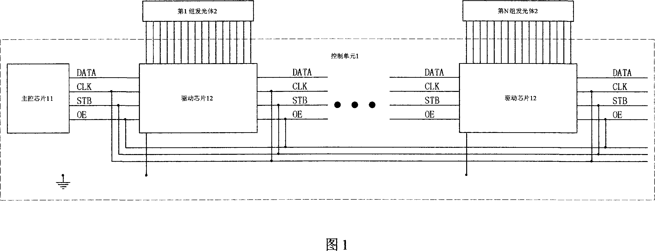
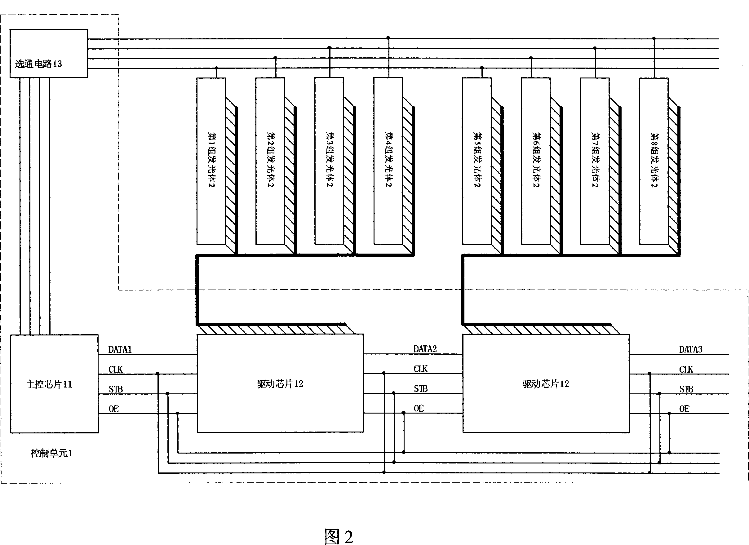
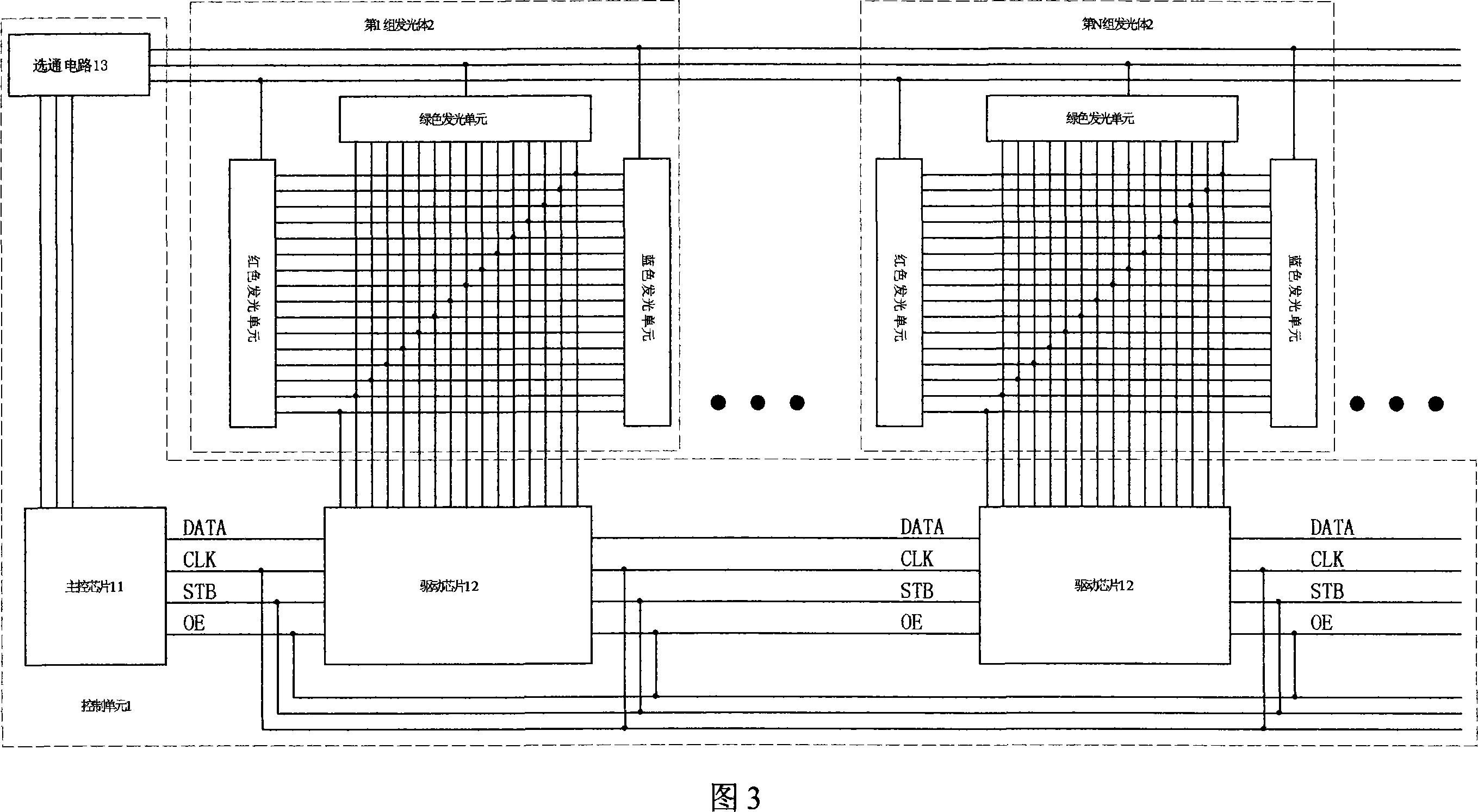
[0016] Referring to Figure 3 and Figure 4 (including Figure 4-1, Figure 4-2 and Figure 4-3), one-third time-sharing LED display control technology, the display screen includes multiple groups of three-color LED light-emitting units The illuminant 2 and the control unit 1, the control unit 1 divides the display cycle of each illuminant 2 into 3 sub-periods according to a certain ratio, and lights up the LED light-emitting units of the corresponding colors in the illuminant 2 in each sub-period. Specifically, the control unit 1 connects the LED light-emitting units of the corresponding colors in the luminous body 2 through the gate output ports of different colors, and in different sub-periods, the gate output ports of the corresponding colors output the control level to the corresponding color LED lighting unit. The corresponding LED display control system using this one-third time-sharing technology includes a control unit 1 and at least one group of luminous bodies 2, and the...


PUM


Abstract

The invention discloses a three-time division LED display control technique and a control system of the same, wherein a screen comprises a plurality of sets of light-emitting bodies consisting of three-color LEDs and comprises a control unit. The control unit divides a display cycle of each light-emitting body into three sub cycles in a certain proportion, and in each sub cycle LEDs of a corresponding color of the light-emitting body are lightened. In the three-time-division technique, gating output ends are corresponding to the LED light-emitting units in terms of number, so the wiring of a circuit is clearer, with the design of a control program simplified at the same time; moreover, time-division sub cycles which are the same or different in length of time can be adopted for red, green and blue three colors, so as to achieve the truest and the most natural blending effect of light. And if a display matrix only requires LED light-emitting units of a certain color to be lightened to display monochromatic patterns and animation in the color, only a gating output end of the color is needed to output a signal.

Description

technical field [0001] The invention relates to a display control technology and an application system thereof, in particular to an LED display control technology using a one-third time-sharing technology and a corresponding control system. Background technique [0002] Lighting decorations and outdoor display screens have been widely used, mainly for festival decoration and advertising display. Existing products mainly use flat-panel dot matrix display, mostly LED dot matrix, and can achieve the effect of color display . At present, each illuminant of the color LED display dot matrix is ​​composed of red, green, and blue primary color LEDs. Static control technology or time-sharing control technology can be used to control the light emission of the above-mentioned LEDs of different colors, and the visual persistence of the human eye can be used. Effect, the three colors of the LED light-emitting unit produce mixed light, so that the display dot matrix can present various c...

Claims


Application Information

Patent Timeline
Patent Type & Authority Applications(China)
IPC IPC(8): H05B37/02G09G3/32G09F9/33
Inventor 陈漱文李浩源卢志林
Owner 陈漱文
Learn More