Liquid container

A liquid container and liquid technology, applied in the direction of container, rigid container, flexible container, etc., can solve the problem of short-term vacuum state of the container, achieve the effect of quiet discharge and avoid sudden change of pressure

Inactive Publication Date: 2010-05-26
郑佑永 +2
View PDF7 Cites 10 Cited by
  • Summary
  • Abstract
  • Description
  • Claims
  • Application Information

AI Technical Summary

Problems solved by technology

This way, outside air cannot enter the container, leaving a brief vacuum inside the container

Method used


Image

  • Liquid container
  • Liquid container
  • Liquid container

Examples


no. 1 example

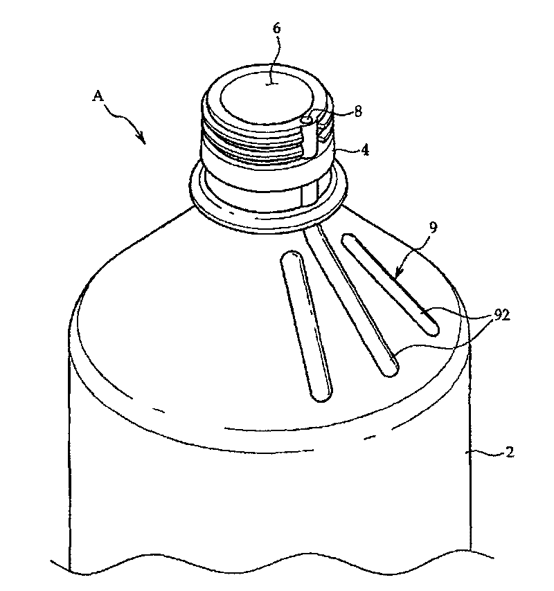
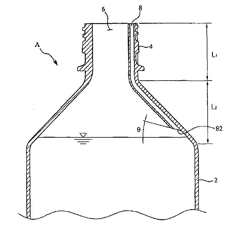
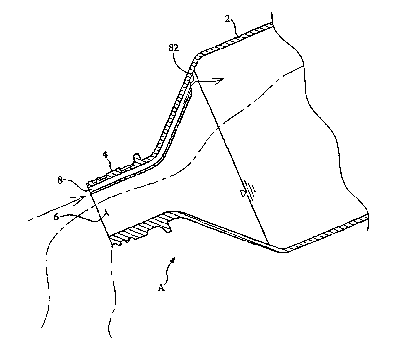
[0029] figure 1 is a perspective view showing main parts of a liquid container according to an embodiment of the present invention; figure 2 Yes figure 1 cross-sectional view of image 3 is displayed figure 1 A cross-sectional view of the liquid container shown in , in use.

[0030] like figure 1 As shown, a liquid container A according to the present invention is used to contain liquid contents, and its basic structure includes: a main body 2; a narrow neck 4 formed on the upper side of the main body 2; an opening 6 formed on the neck 4 , for draining the liquid contents; and a cap (not shown), which is coupled with the opening 6 .

[0031] Furthermore, the liquid container A of the present invention also has an air passage 8 formed in the upper portion of the main body 2 and facing the opening 6 . The air channel 8 is divided into two sections, the first section ( L1 ) extends from the upper part to the lower part of the neck 4 , and the second section ( L2 ) is locat...

no. 2 example

[0038] Figures 4 to 6 The structure and usage state of a liquid container according to another embodiment of the present invention are shown.

[0039] The liquid container B according to this embodiment includes: a main body 10; a narrow neck 14 extending to the upper side of the main body 10; and an opening 12 formed at the neck 14 for discharging liquid contained in the main body 10. Contents. In addition, the liquid container B also has an air passage 13 formed in the wall of the container B and extending from the upper portion of the main body 10 to the opening 12 . Through the opening 12 and the inner surface of the main body 10, the air passage 13 can communicate with the inside of the container B. As shown in FIG. The air channel 13 can be integrally formed in the inner wall of the container B, or installed in the container B in a detachable manner.

[0040] For example, if the air channel 13 is integrally formed in the inner wall of the container B, it can be manuf...

no. 3 example

[0046] Figure 7 is a perspective view showing main parts of a liquid container according to yet another embodiment of the present invention; Figure 8 is along Figure 7 A cross-sectional view made on line II-II.

[0047] As shown in the figure, the basic structure of the liquid container C includes a main body 20 and an opening 22, and figure 1 and Figure 4 similar in. In this embodiment, the liquid container C further includes an inner body 30 coupled to the inner surface of the body 20 and the opening 22 .

[0048] The inner body 30 is placed on the upper side of the body 20 and extends to the opening 22 . The inner body 30 is generally funnel-shaped. Preferably, the inner body 30 can be forcibly inserted into the body 20 . The inner body 30 has a connecting opening 32 which can communicate with the opening 22 and the inside of the main body 20 when the inner body 30 is inserted into the opening 22 . In addition, a plurality of partition protrusions 34 are formed ...


PUM


Abstract

Disclosed is a liquid container for containing liquid contents. The liquid container comprises a body with a desired volume for containing liquid contents; a narrow neck formed at an upper side of thebody; an opening formed at an inside of the neck so as to be communicated with an inside of the body; and an air path extended from the upper side of the body to an upper side of the neck so as to beopened at upper and lower end thereof so that an entrance of the opening is communicated with an inside of the body, wherein a lower opening of the air path has an inclined section which is inclinedupward at a desired angle relative to a reference surface of the liquid contents in the body. And, the air path has a length so that the lower opening thereof is not contacted with the reference surface of the contents. According to the present invention, when a user tilts the container after removing the cap so as to pour out the contents, since the external air can be smoothly entered through the air path extended, a sudden pressure change in the container is prevented. Thus, the contents can be smoothly and quietly discharged without sputtering and splashing about inside.

Description

technical field [0001] The present invention relates to a liquid container in which liquid contents can be held, and more particularly, to a liquid container capable of smoothly discharging the liquid contents in any orientation without splashing liquid or emitting noise. Background technique [0002] In general, glass bottles or plastic containers, such as PET (polyethylene terephthalate) bottles, have been widely used as containers for liquid contents such as mineral water and various beverages. These liquid containers generally include: a body, which may have different volumes; a narrow neck, which is formed on the upper side of the body; an opening, which is formed on the upper side of the neck; and a cap, which is threaded onto the opening. The contents in the container can be discharged to the outside by the opening / closing operation of the lid. [0003] When a liquid container is tipped to one side in order to pour out the contents, the contents temporarily block th...

Claims


Application Information

Patent Timeline
Patent Type & Authority Patents(China)
IPC IPC(8): B65D23/04
CPCB65D23/04B65D2205/00B65D25/02B65D25/38B65D33/01
Inventor 赵敬熙
Owner 郑佑永
Why Eureka
Try Eureka