Liquid discharging device

A liquid discharge and driving device technology, applied in the direction of preventing condensed water, etc., can solve the problems of large installation space, large volume of liquid discharge device, splashing, etc., achieve the effect of simple structure of parts, improve drainage efficiency, and avoid pressure loss

Inactive Publication Date: 2009-11-25
ZHEJIANG SANHUA INTELLIGENT CONTROLS CO LTD
View PDF0 Cites 8 Cited by
  • Summary
  • Abstract
  • Description
  • Claims
  • Application Information

AI Technical Summary

Problems solved by technology

Moreover, when the liquid discharge device stops working, the water in the outlet pipe will flow back into the pump chamber 23a. At this time, the water in the pump chamber 23a will also be ejected from the gap between the rotating shaft 7a and the shaft hole 6a, splashing to the drive motor. 4a, causing great security risks
[0009] In addition, the drive motor 4a and the pump body are of a separate structure, resulting in a large volume of the liquid discharge device and occupying a large installation space

Method used


Image

  • Liquid discharging device
  • Liquid discharging device
  • Liquid discharging device

Examples


Embodiment Construction

[0032] In order to enable those skilled in the art to better understand the technical solutions of the present invention, the present invention will be further described in detail below in conjunction with the accompanying drawings and specific embodiments.

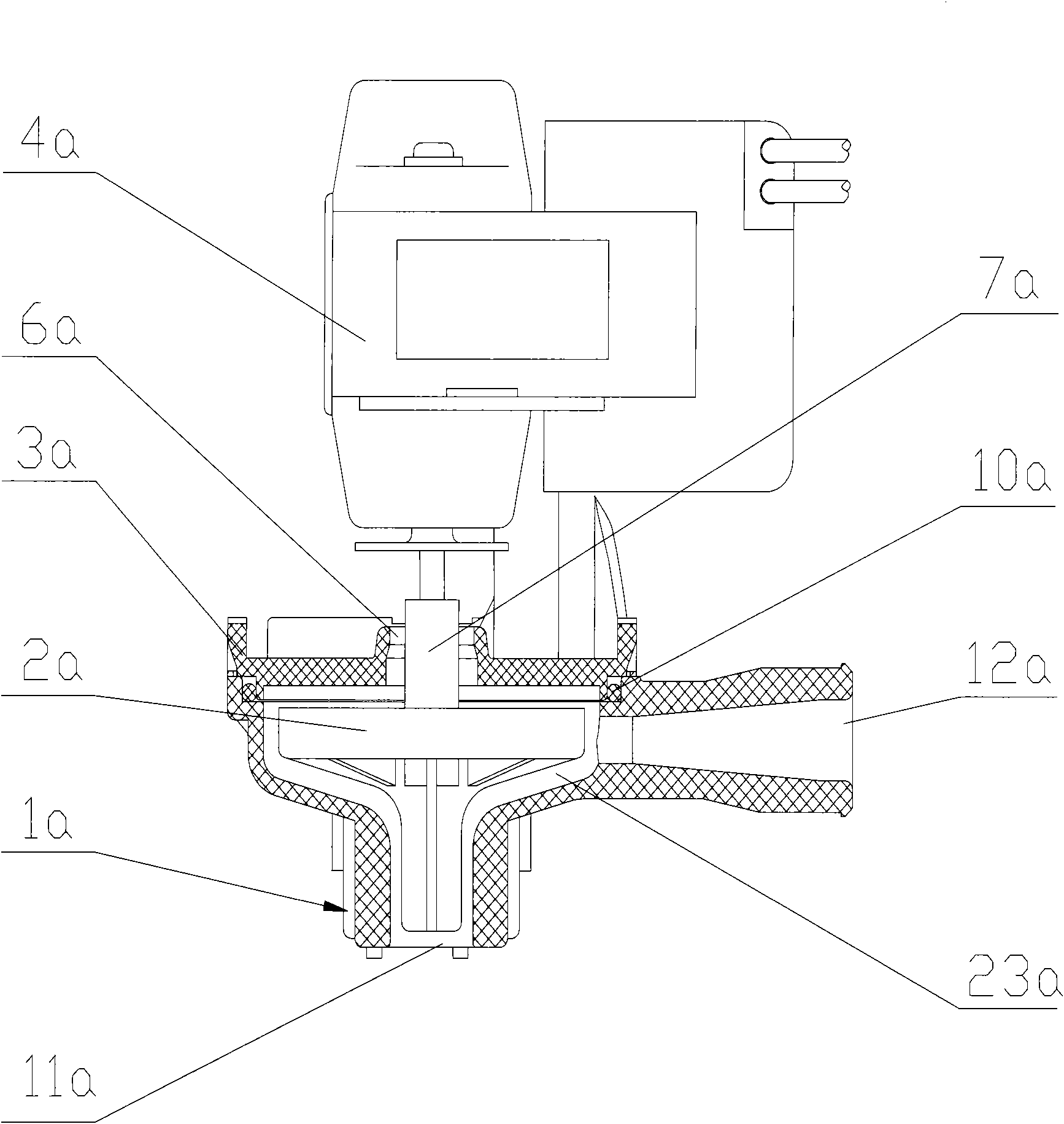
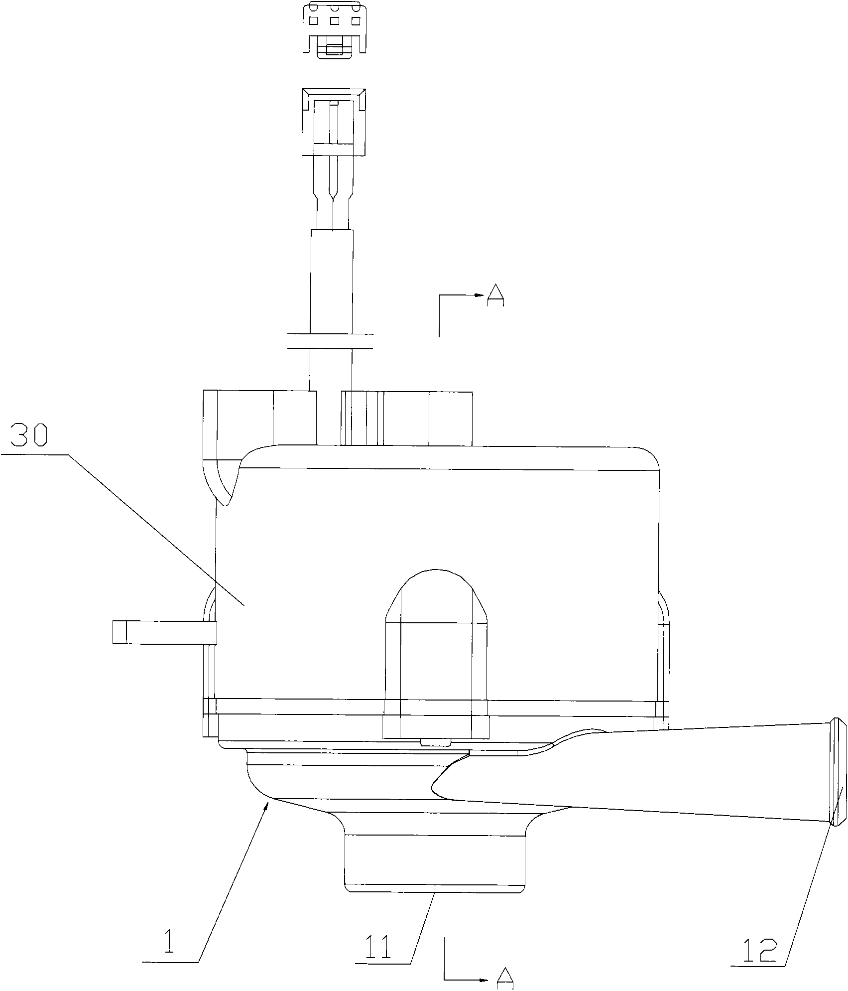
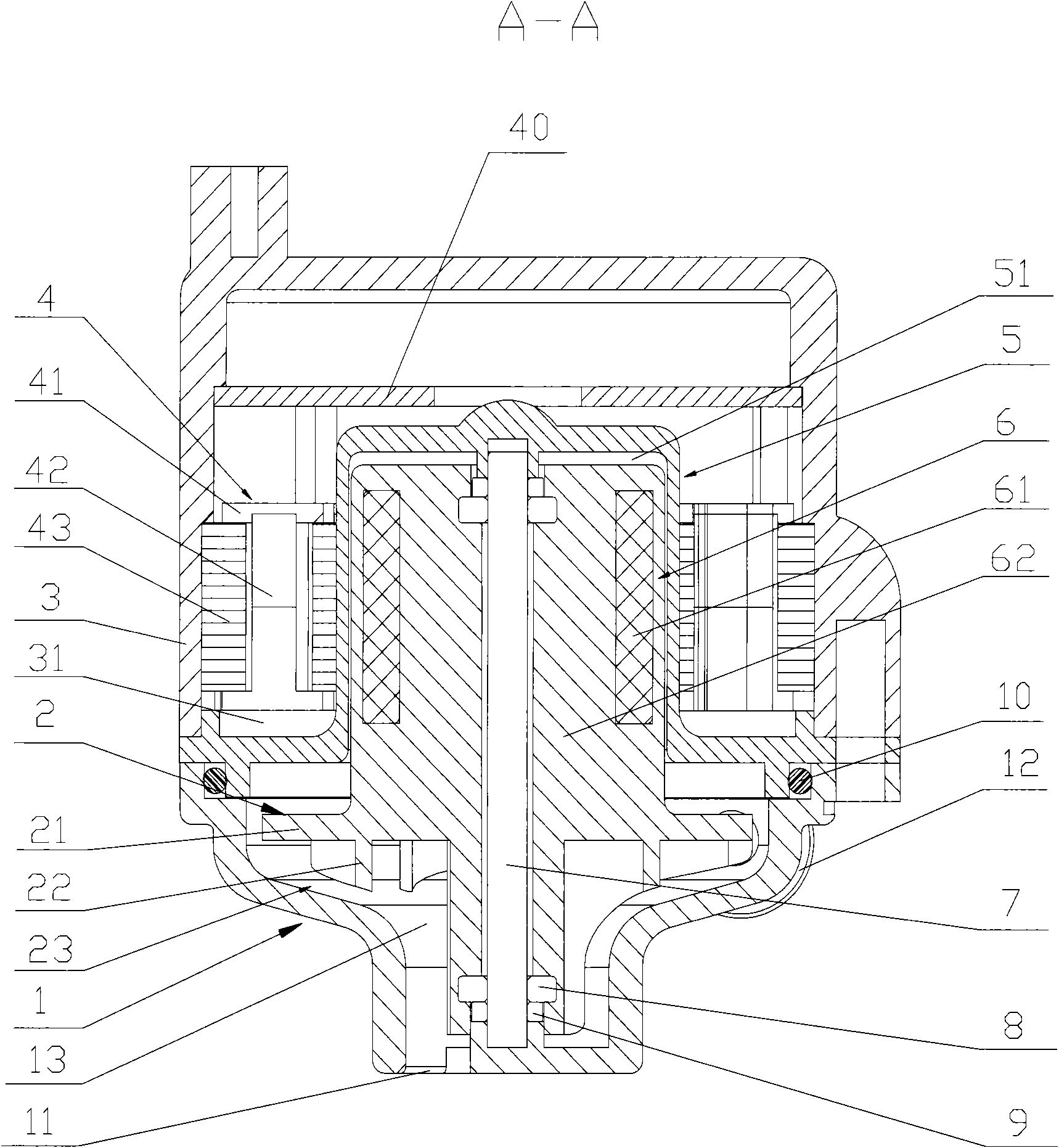
[0033] refer to figure 2 , figure 2 It is a structural schematic diagram of the first embodiment of the liquid discharge device of the present invention; image 3 for along figure 2 Sectional view of line A-A.

[0034] like figure 2 and 3 As shown, the liquid discharge device provided in this embodiment includes a pump body 1 , an impeller 2 , a driving device 30 and an isolation cover 5 . The lower end of the pump body 1 has a liquid inlet 11, and its side wall has a liquid outlet 12 ( figure 2 As shown), the pump body 1 has an open inner cavity 13 . The driving device 30 includes a housing 3, a stator 4 installed in the housing 3, and a rotor 6 arranged in the isolation cover 5. The liquid discharge device a...


PUM


Abstract

The invention discloses a liquid discharging device comprising a pump body with a liquid inlet and a liquid outlet, an impeller and a drive device, wherein the drive device comprises a stator and a rotor. The liquid discharging device is characterized by also comprising a separating cover for separating the rotor and the stator, wherein the separating cover is in sealing connection with the pump body; the inner cavity of the separating cover and the inner cavity of the pump body form a sealed pump cavity; the rotor and the impeller are installed inside the pump cavity, and the stator is installed outside the pump cavity, therefore, when the liquid discharging device works, the impeller works in a sealed environment, thereby avoiding the problem of pressure loss caused by a clearance between a rotating shaft and a shaft hole of the impeller in the prior art and improving the liquid discharging efficiency of the liquid discharging device.

Description

technical field [0001] The present invention relates to a liquid discharge device, in particular to a liquid discharge device used in a refrigeration system, such as a drain pump for an air conditioner. Background technique [0002] During the working process of the refrigeration system, such as when the air conditioner is working (refrigeration, dehumidification), due to the cooling effect of the heat exchanger on the surrounding air, a large amount of condensed water will be generated on the surface of the heat exchanger. When the level is high, it will drip into the condensed water pan under the heat exchanger, so it is necessary to install a liquid discharge device in the water pan to discharge the condensed water in the water pan to the outside. [0003] refer to figure 1 , figure 1 A schematic structural view of a liquid discharge device in the prior art is shown. [0004] like figure 1 As shown, the liquid discharge device includes a pump body, an impeller 2a inst...

Claims


Application Information

Patent Timeline
Patent Type & Authority Applications(China)
IPC IPC(8): F24F13/22
Inventor 陈雨忠赵剑锋冯旭光
Owner ZHEJIANG SANHUA INTELLIGENT CONTROLS CO LTD
Why Eureka
Try Eureka