Tensioning system

A tensioning system and tool technology, applied in the direction of transmission, belt/chain/gear, mechanical equipment, etc., can solve the problem of large lubricant flow and achieve the effect of reducing wear

Inactive Publication Date: 2008-08-20
SCHAEFFLER KG
View PDF2 Cites 10 Cited by
  • Summary
  • Abstract
  • Description
  • Claims
  • Application Information

AI Technical Summary

Problems solved by technology

The disadvantage of this type of traction tool lubrication is that it requires a large amount of lubricant flow in order for all spray holes to deliver enough lubricant to the control chain at the same time

Method used


Image

  • Tensioning system
  • Tensioning system
  • Tensioning system

Examples


Embodiment Construction

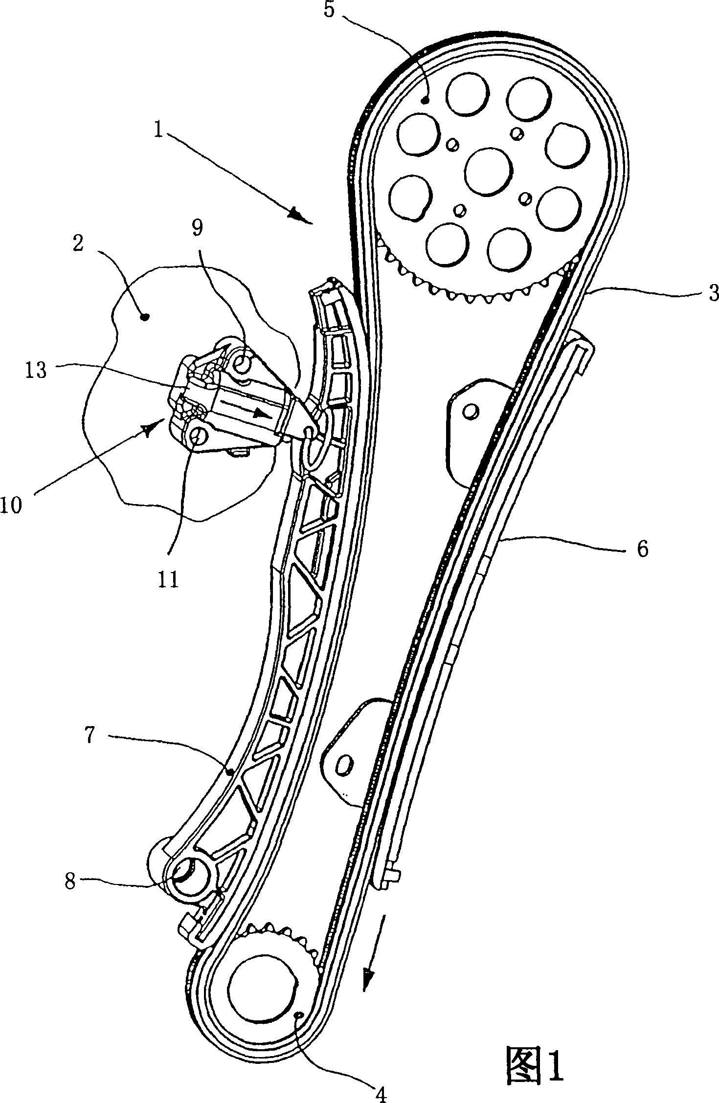
[0024] FIG. 1 shows a traction gear transmission 1 of an internal combustion engine 2 . Here, traction means 3 designed as a chain connects output gear 4 , which is rotationally rigidly connected to the crankshaft of internal combustion engine 2 , with drive gear 5 , via which a camshaft (not shown) of internal combustion engine 2 is driven. The traction means 3 running in the clockwise direction is guided on guide rails 6 in the region of the traction section. Furthermore, the traction means 3 is operatively connected in the idle section to a tensioning rail 7 arranged so as to be rotatably limited around a pivot axis 8 . At the end remote from the pivot axis 8 , the tensioning rail 7 is assigned a hydraulically acting tensioning system 10 which is detachably fastened to the internal combustion engine 2 via fastening elements 9 , 11 , in particular screw connections. In the operating state, tensioning system 10 is acted upon by a hydraulic fluid, in particular a lubricant wh...


PUM


Abstract

Hydraulic tensioning system (10) for a flexible drive (1), in which a longitudinally displaceable piston (12) guided in a housing (13) is subjected to the force of a hydraulic fluid. For this purpose, the hydraulic fluid passes via a feed bore (19) into a supply chamber (20) of the housing (13). A portion of the hydraulic fluid is diverted via an injection nozzle (25a) of the housing (13) for the purpose of acting on the flexible drive element (3).

Description

technical field [0001] The invention relates to a hydraulic tensioning system for a traction means transmission of an internal combustion engine, in particular a traction means embodied as a chain. The tensioning system comprises a housing which is fastened in a fixed position on the internal combustion engine and forms a hydraulic cylinder, in which a piston is guided which is acted upon by a spring element and hydraulic fluid. In this case, the piston is directly or indirectly operatively connected to a tensioning rail guided on the traction means. The hydraulic fluid for acting on the piston is conducted via the feed opening into the housing, wherein a part of the hydraulic fluid can be used for lubricating the traction gear transmission. Background technique [0002] This tensioning system is used to ensure sufficient pretensioning and vibration-free transmission of the pulling means. The known tensioning system comprises a piston guided in and protruding from a housin...

Claims


Application Information

Patent Timeline
Patent Type & Authority Applications(China)
IPC IPC(8): F16H7/08
CPCF16H2007/0859F16H7/0848F16H7/0836F16H2007/0812F16H2007/0806F16H2007/0893F16H7/08
Inventor 托马斯·乌莱因
Owner SCHAEFFLER KG
Why Eureka
Try Eureka