Controlling the gap geometry in an eccentric screw pump

a technology of eccentric screw and gap geometry, which is applied in the direction of rotary/oscillating piston pump components, machines/engines, liquid fuel engines, etc., can solve the problems of further wear, and achieve the effects of preventing wear, reducing wear, and reducing constriction

Active Publication Date: 2022-03-29
VOGELSANG GMBH & CO KG
View PDF26 Cites 0 Cited by
  • Summary
  • Abstract
  • Description
  • Claims
  • Application Information

AI Technical Summary

Benefits of technology

[0012]The invention recognizes that all wear can be prevented, or reduced, if the constriction is expanded during operation and thereby the gap geometry can be adapted to the operating conditions and thus optimized. The present invention therefore proposes an adjusting device implemented for expanding the constriction between the rotor and stator. If the constriction is further expanded, then contact at lower pretension or no contact is present, and thereby less friction between the rotor and stator, in turn leading to lower wear. When pumping liquid, an additional cooling effect occurs, so that the parts can again cool down when the pretension is reduced. It is thereby also possible, for example, to adjust a larger gap when starting up the progressive cavity pump in order to keep friction low in the dry state. It is also possible to operate the progressive cavity pump in an energy-saving manner by adjusting to the optimal overall efficiency, taking into consideration the volumetric efficiency and friction losses. Merely slightly expanding the constriction, however, is advantageous for media sensitive to shear. The progressive cavity pump can thus be adjusted by means of the invention to the media being transported.
[0040]In a further preferred embodiment, the method further comprises: determining a transported volume of liquid per revolution of the rotor; and relatively axially displacing the rotor and stator depending on the liquid volume determined. A low volume of transported liquid per revolution of the rotor indicates that a relatively high proportion of gas is being transported. Transporting gas prevents lubricating between the parts in contact with each other, and prevents cooling. In this case, when a relatively large amount of gas is transported and little liquid per revolution of the rotor, it is preferable that the constriction is expanded in order to thus prevent wear.

Problems solved by technology

The increased pretension then leads to further wear.

Method used


Image

  • Controlling the gap geometry in an eccentric screw pump
  • Controlling the gap geometry in an eccentric screw pump
  • Controlling the gap geometry in an eccentric screw pump

Examples


Embodiment Construction

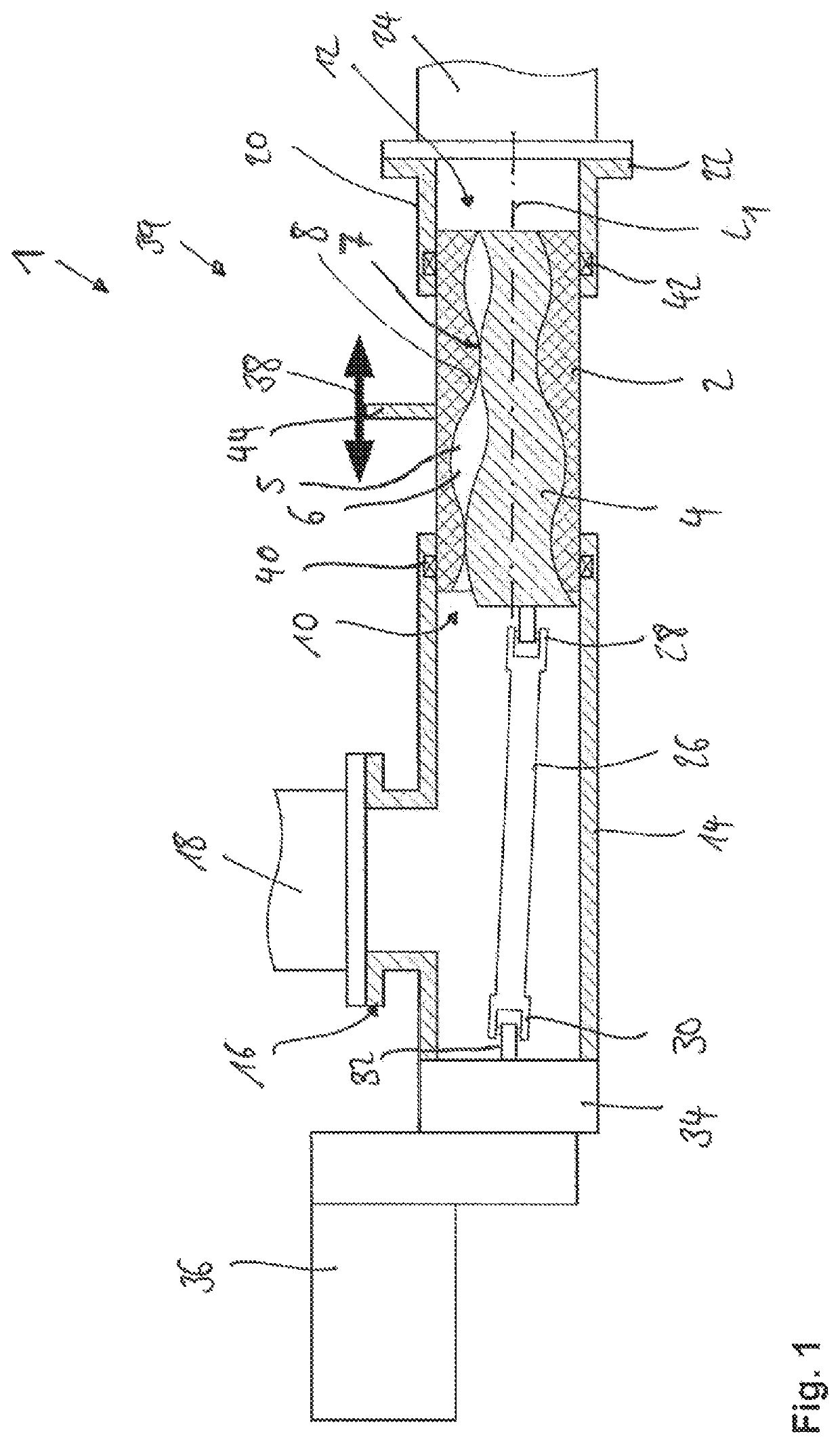
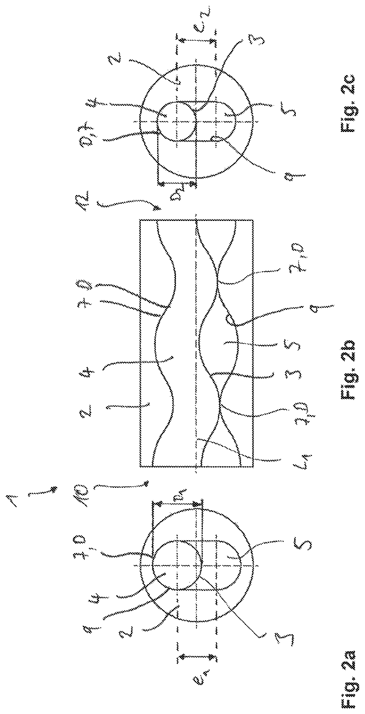
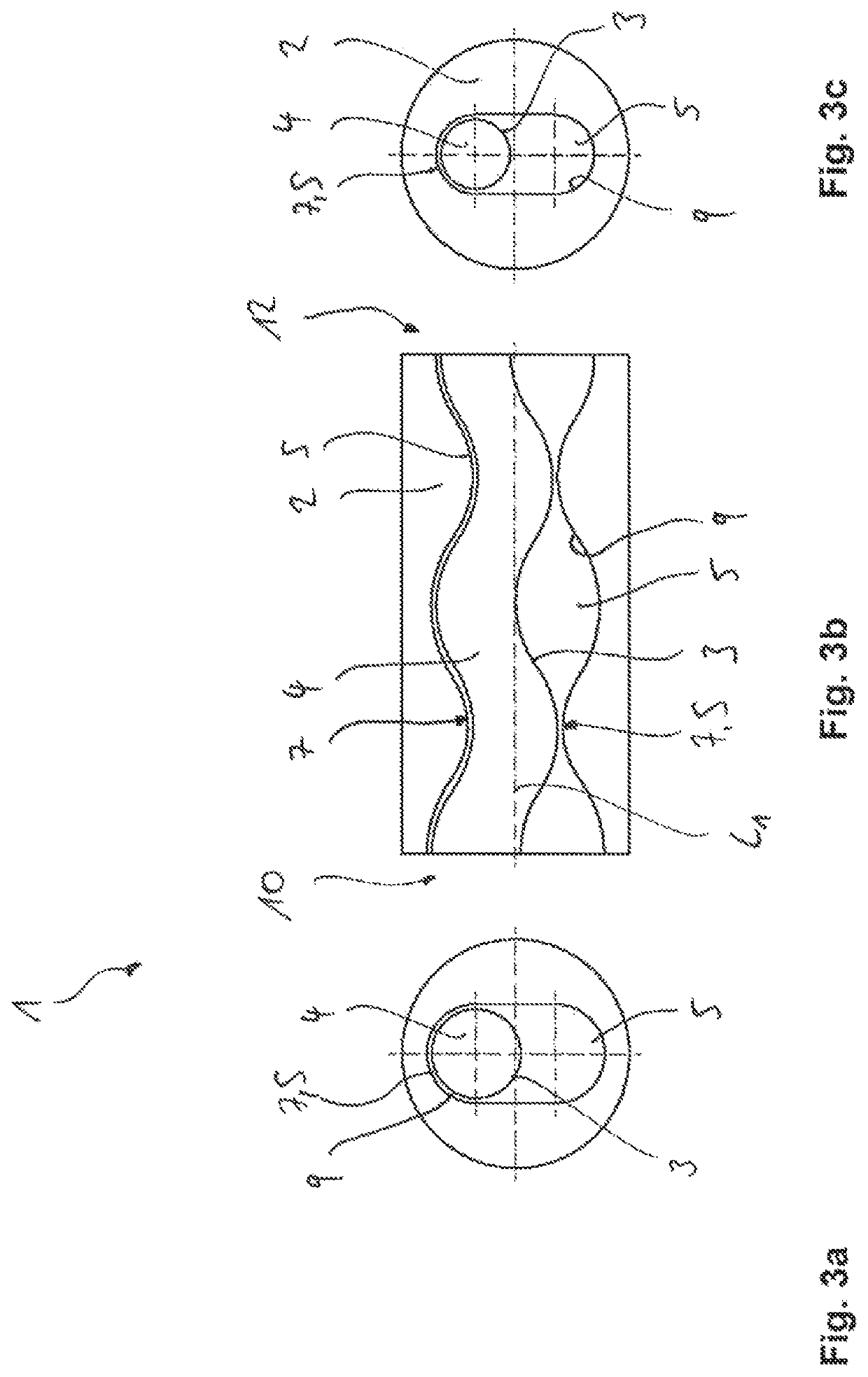
[0057]A progressive cavity pump 1 comprises a stator 2 and a rotor 4. The stator has a center axis L1 extending centrally through an inner cavity 6 of the stator 2. The stator 2 comprises an inner wall 8 bounding the cavity 6 and formed of an elastomer material. An inner contour 9 of the inner wall 8 is formed so as to define a double helix. The rotor 4 is also helical in overall design, wherein the pitch of the helix of the stator 2 has double the pitch with respect to the rotor 4. Individual chambers 5 separated by a constriction 7 are thus formed.

[0058]The stator 2 further comprises an inlet 10 and an outlet 12. The inlet 10 is connected to an inlet housing 14 comprising an inlet flange 16 to which an inlet pipe 18 is connected. The outlet 12 further has an outlet housing 20 comprising an outlet flange 22 to which an outlet pipe 24 is connected.

[0059]A drive shaft 26 extends through the inlet housing 14 and is connected to the rotor 4 by means of a first Cardan joint, and connect...


PUM


Abstract

A progressive cavity pump for transporting a liquid containing solids comprises a helical rotor, a stator having an inlet and an outlet, within which the helical rotor is rotatably disposed about a longitudinal axis of the stator, and comprising a helical inner wall corresponding to the helical rotor. The helical rotor comprises a shape tapering down toward the outlet or inlet, and the helical rotor and stator are disposed relative to each other and implemented such that at least one chamber is formed for transporting the liquid, and the chamber is cut off by a constriction. The progressive cavity pump includes an adjusting device for adjusting a relative axial position of the helical rotor and stator, wherein the adjusting device is implemented for expanding the constriction between the helical rotor and stator.

Description

CROSS-REFERENCE TO FOREIGN PRIORITY APPLICATION[0001]The present application claims the benefit under 35 U.S.C. §§ 119(b), 119(e), 120, and / or 365(c) of PCT / EP2018 / 050986 filed Jan. 16, 2018, which claims priority to German Application No. 102017100715.6 filed Jan. 16, 2017.FIELD OF THE INVENTION[0002]The invention relates to a progressive cavity pump for transporting fluids loaded with solids, having a helical rotor, a stator having an inlet and an outlet, in which the rotor is rotatably disposed about a longitudinal axis of the stator, and comprising a helical inner wall corresponding to the rotor. The rotor comprises a shape tapering down toward the outlet or inlet, preferably conical, and / or a variable eccentricity, and the rotor and stator are disposed relative to each other and implemented such that at least one chamber is formed for transporting the liquid, and the chamber is cut off by a constriction, particularly a sealing line. The invention further relates to a method for...

Claims


Application Information

Patent Timeline
Patent Type & Authority Patents(United States)
IPC IPC(8): F01C1/10F03C2/00F03C4/00F04C2/00F04C2/107F04C3/06F04C14/06F04C15/00
CPCF04C2/1073F04C3/06F04C14/06F04C15/003F04C2250/201F04C2/107F04C2240/10F04C2240/20F04C2/1071F04C15/0003
Inventor KRAMPE, PAULROLFES, MICHAEL
Owner VOGELSANG GMBH & CO KG
Why Eureka
Try Eureka