Systems and methods of forced air induction in internal combustion engines

a technology of forced air induction and internal combustion engine, which is applied in the direction of combustion engine, crankcase ventillation, machine/engine, etc., can solve the problems of large engine weight, increased construction cost, and increased horsepower, and all such devices are generally fairly complex in design

Active Publication Date: 2020-09-15
NAUTILUS ENG LLC
View PDF32 Cites 0 Cited by
  • Summary
  • Abstract
  • Description
  • Claims
  • Application Information

AI Technical Summary

Benefits of technology

[0010]As is discussed above, some embodiments of the inventive concept utilize centrifugal force to remove lubricant / fuel or other contaminants from the air as it travels from within the crankcase chamber to the intake of the combustion chamber. In some embodiments the centrifugal force is obtained by directing the air flow path from the crankcase chamber through a portion of a conduit that is at least partially curved. The curvature of the conduit results in higher density material, such as lubricant or fuel (or other contaminants), to be forced toward the outer circumference or arc of the curve and to exit the conduit through one or more return conduits or ports located along such outer circumference of the conduit. In some embodiments, one or more channels are formed in the conduit to direct lubricant or fuel (or other contaminants) into the return ports. In some embodiments, the at least partially curved conduit is curved in a manner to generally correspond to a logarithmic spiral, such as that of a nautilus shell. Nevertheless, it will be appreciated that in some such embodiments, the curvature will vary at least partially from the logarithmic spiral, while in other embodiments the curvature will not follow a logarithmic spiral at all. For example, in some embodiments, the curvature follows the logarithmic spiral closer to the interior, but becomes more compressed (e.g. does not grow logarithmically) towards the interior of the spiral so as to maximize the centrifugal benefits within a smaller footprint.
[0011]It will be appreciated that in some embodiments, the conduit of the instant inventive concept is located at least partially within the crankcase chamber. In some such embodiments, the at least partially curved portion of the conduit is located within the crankcase chamber, with another section that extends through a port in the crankcase chamber to the exterior of the crankcase and ultimately communicating with the intake into the combustion chamber of the engine. In other embodiments, the conduit is at least generally located at the exterior of the crankcase chamber with a crankcase intake portion of the conduit in fluidic communication with a port extending into the crankcase chamber. In some embodiments of the inventive concept, the crankcase intake portion of the conduit includes a diameter that is slightly smaller than the diameter of the conduit. This constriction increases vacuum developed during flow of air within the conduit which enhances the evacuation of lubricant, fuel or other debris through the return conduits and into the crankcase chamber.
[0014]In some embodiments, the volume of the conduit is determined based upon the volume of air in the crankcase under the piston. In some such embodiments, the volume of the conduit below the combustion chamber intake is generally equal to the volume of air that is compressed by the piston during its down stroke. This allows the oscillating air within the conduit to function to compress the fresh air charge drawn in from the atmospheric intake efficiently, while at the same time preventing air from the crankcase from being directed into the combustion chamber. In other embodiments, the volume of the conduit below the combustion chamber intake is less than the volume of air that is compressed by the piston during its down stroke, such that at least some air from the crankcase is directed into the combustion chamber. It will be appreciated that in some embodiments the volume of the conduit is varied or determined to operate with a specific crankcase volume below the piston, while in other embodiments the volume of the crankcase (below the piston) itself is a function of the volume of the conduit. In some embodiments the volume of the conduit is varied to provide a specific amount of desired boost. In some embodiments the volume of the crankcase (below the piston) is minimized to result in increased pressure within the conduit.
[0015]In some embodiments of the inventive concept the air flow path through the conduit is entirely open and unobstructed at all times by any solid mechanical object located in the flow path, with the exception being in some embodiments a check valve (reed valve, other one-way, or two-way controllable valve structure now known or hereinafter developed) that prevents any (or partially restricts) air flow from the conduit out of the atmospheric intake.
[0017]Crankcase air and freshly drawn induction air share the same flow path without an intervening mechanical barrier, yet without contamination of the freshly drawn induction air by oil entrained within crankcase air. The flow path includes a first section in fluid communication with the crankcase chamber, a second section in fluid communication with the first section and with an intake port of the engine, and a third section in fluid communication with the first section, the second section, and the atmosphere outside the engine. A check valve in the third section enables incoming air to flow from the third section into the first section and the second section, and prevents captured air from flowing ineffectually back into the third section while under pressure from the crankcase during cylinder charging. The system in some embodiments includes an oil separator for removing oil droplets which could contaminate fresh induction air. In some embodiments, the oil separator does not introduce a mechanical obstruction into the air flow path.

Problems solved by technology

Unfortunately, bigger engines weigh more and cost more to build and maintain.
This results in a larger explosion in the combustion chamber and greater horsepower.
All such devices are generally fairly complex in design, increasing costs and routine maintenance requirements.
In addition, such devices typically tend to extend into the engine bay of the vehicle in which the engine is located.
Thus, bulky, complex superchargers are undesirable, impractical, or even not possible in many applications.
Nevertheless, prior art systems that utilize the crankcase chamber to increase boost have encountered several disadvantages.
For example, utilizing pressure generated from the crankcase chamber often causes droplets of lubricant or fuel from within the crankcase chamber to be directed into the combustion chamber.
Such droplets tend to burn incompletely, leading to increased emissions of hydrocarbons, smoke, volatile organic compounds, and carbon monoxide, as well as formation of objectionable carbon deposits on the combustion chamber, piston ring, piston, and valve surfaces.
Nevertheless, prior to the advent of the instant inventive concept, such systems have required additional complexity and cost, and increases demands on space.

Method used


Image

  • Systems and methods of forced air induction in internal combustion engines
  • Systems and methods of forced air induction in internal combustion engines
  • Systems and methods of forced air induction in internal combustion engines

Examples


Embodiment Construction

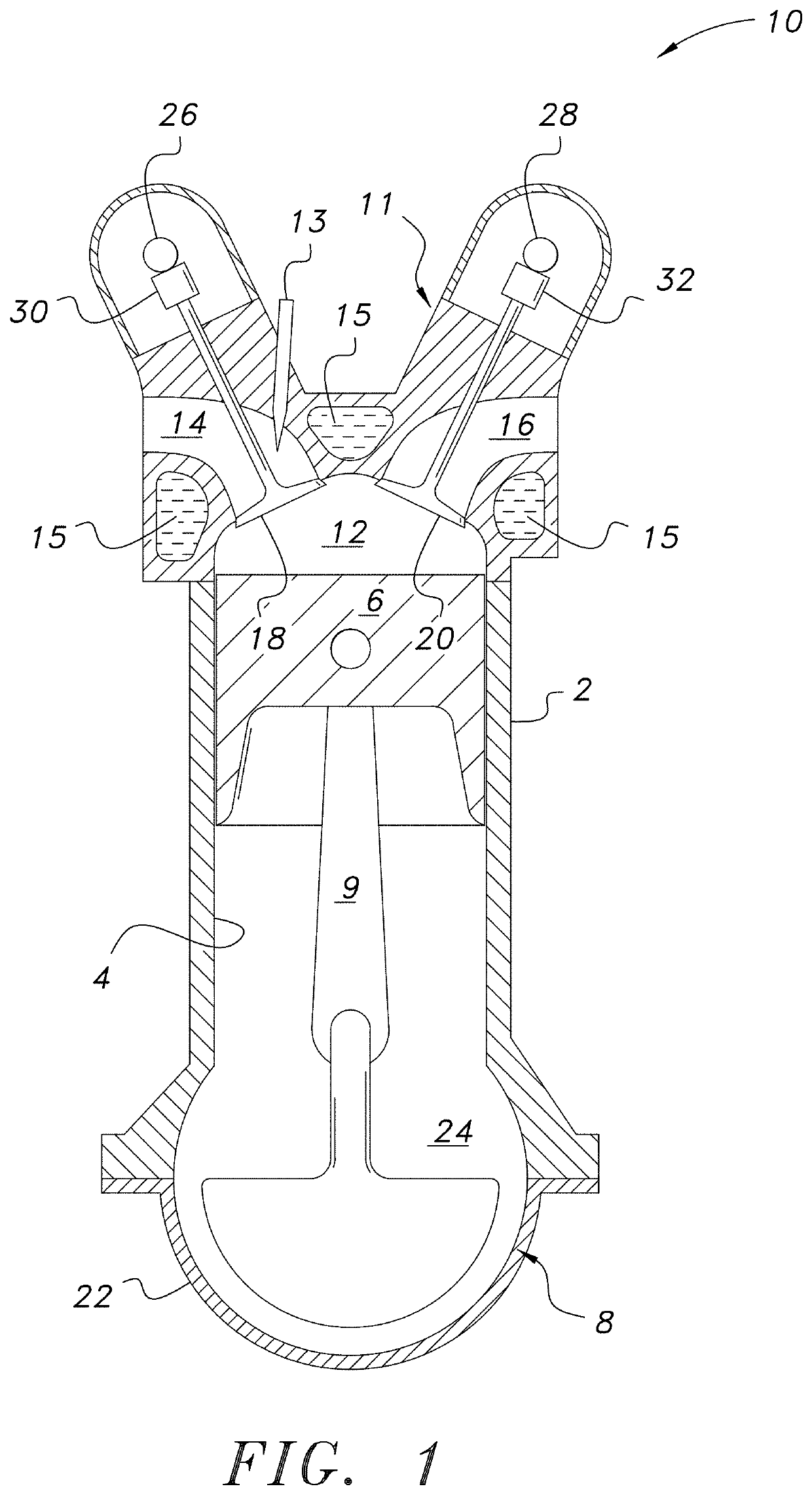
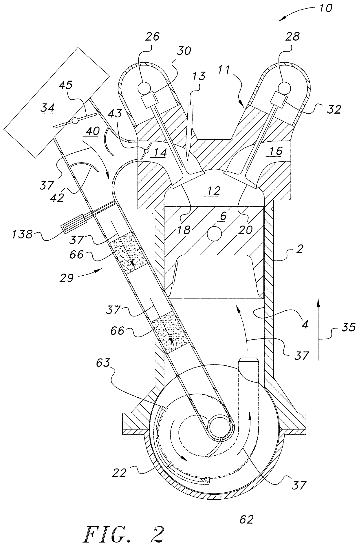
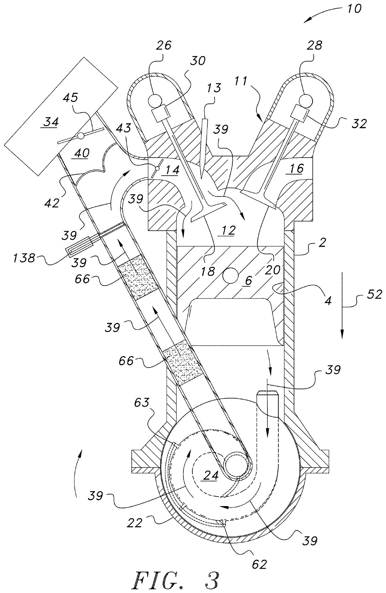
[0048]As required, a detailed embodiment of the present inventive concept is disclosed herein; however, it is to be understood that the disclosed embodiment is merely exemplary of the principles of the inventive concept, which may be embodied in various forms. Therefore, specific structural and functional details disclosed herein are not to be interpreted as limiting, but merely as a basis for the claims and as a representative basis for teaching one skilled in the art to variously employ the present inventive concept in virtually any appropriately detailed structure.

[0049]It will be appreciated that the drawings included herein are intended for representative purposes only of the inventive concept, and therefore in some instances may not be shown to scale and / or may otherwise include representative depictions of components and / or their arrangements that may vary significantly from the respective component designs and / or arrangements included in three-dimensional models or manufactu...


PUM


Abstract

Apparatuses, systems and methods for utilizing crankcase compression air to effect forced air induction (i.e. “boost”) into the combustion chamber of an internal combustion engine is provided. In some embodiments, the apparatuses are a supercharger apparatus that is attached to an existing engine. In other embodiments, the supercharger components are located within the structure of a novel engine itself. An embodiment of the apparatus includes a conduit that includes three inlets: 1) an inlet that is capable of being placed in fluidic communication with the crankcase chamber of an engine; 2) an inlet that is capable of being placed in fluidic communication with an intake to a combustion chamber of the engine; and 3) an inlet in fluidic communication with the atmosphere.

Description

CROSS-REFERENCE TO RELATED APPLICATIONS[0001]This application is a United Sates National Stage of Patent Cooperation Treaty Application No. PCT / US2014 / 064866 filed Nov. 10, 2014, which claims priority to U.S. Provisional Patent Application Serial Nos.: 61 / 903,114, filed Nov. 12, 2013; 61 / 921,604, filed Dec. 30, 2013; 61 / 924,160, filed Jan. 6, 2014; 61 / 929,866, filed Jan. 21, 2014; 61 / 975,209, filed Apr. 4, 2014; 61 / 993,646, filed May 15, 2014 and 62 / 060,977, filed Oct. 7, 2014, the entire disclosures of which are incorporated herein by reference.FIELD OF THE INVENTION[0002]The present inventive concept relates generally to apparatuses, systems and methods for effecting forced air induction of combustion air into an internal combustion engine. More particularly, the present inventive concept is concerned with apparatuses, systems and method for utilizing crankcase compression of air to effect forced air induction of combustion air into one or more cylinders of an internal combustion ...

Claims


Application Information

Patent Timeline
Patent Type & Authority Patents(United States)
IPC IPC(8): F02B25/06F02B33/26F02B33/28F01M13/02F01M11/08F02B33/04
CPCF01M13/028F02B33/28F02B33/04F02B33/26F01M11/08
Inventor RILEY, MATTHEW
Owner NAUTILUS ENG LLC
Why Eureka
Try Eureka