High volume low speed fan

a low-speed, fan technology, applied in the direction of liquid fuel engines, marine propulsion, vessel construction, etc., can solve the problems of insufficient air circulation in large open areas, difficulty in circulating air in certain areas, and difficulty in interior climate control and air circulation, so as to increase air volume and circulation, increase efficiencies, and reduce the effect of weigh

Active Publication Date: 2015-04-21
SKYBLADE FAN
View PDF32 Cites 44 Cited by
  • Summary
  • Abstract
  • Description
  • Claims
  • Application Information

AI Technical Summary

Benefits of technology

[0008]The present disclosure addresses these needs and issues by providing an HVLS fan system incorporating STOL technology in a system that increases air volume and circulation while also increasing efficiencies and which does not add significant costs, weight, or manufacturing complexity to this system.
[0009]It is therefore an object of the disclosure to take advantage of STOL technology and thus increase efficiency of an HVLS fan system. It is a further object of the disclosure to provide greater efficiency in the movement of air in the HVLS system. It is an additional object of the disclosure to provide an economical and lightweight solution to better circulate air in large areas. Another object of the disclosure is to provide a safety mechanism for preventing injury or damage in the event of a failure in the HVLS fan.
[0010]The present disclosure provides an HVLS fan system utilizing STOL technology and having better efficiency, including an airfoil form adapted to provide higher airflow at lower circulation rates while decreasing drag on the airfoils and increasing efficiencies. The system also includes an airfoil profile consistent with STOL technology. More particularly, an airfoil utilizing an EPPLER 420 or substantially similar airfoil design. In addition, the system includes a wing tip advantageously formed to reduce drag of the airfoil. Further, the system employs a hub displacing the airfoil at an angle most suitable for maximizing the benefits of the STOL technology. More particularly, this includes a hub providing an attachment angle of between seven and ten degrees to the airfoil, and even more particularly eight degrees to the airfoil. Together, the disclosure provides an HVLS fan system offering improved efficiency, reduced drag, and increased air flow for the benefit of better circulating air in a large open area.
[0011]In addition, the system includes a safety system including attachment of a retaining member, one for each airfoil, on the hub that passes through a retaining bracket in a manner that in the event of the airfoil becoming dislodged from the hub or the hub itself becoming disconnected from the drive system prevents the hub and / or the airfoils from falling. The retaining brackets do not touch or otherwise notably increase air resistance in the system but provide for an important safety measure where failure can cause catastrophic consequences. Another safety aspect is a series of overlapping brackets which mount on the top of the airfoils which interlock each of the airfoils to the one next to it. This will prevent an airfoil from becoming dislodged from the system in the case of failure. In addition, guy wires connect the frame of the HVLS fan system to a support member such as a ceiling support beam.

Problems solved by technology

Interior climate control and air circulation is difficult in certain applications, particularly including large open structural areas such as found in a factory or warehouse setting.
This difficulty is encountered in both hot and cold seasonal conditions, where heat during cold weather heating migrates towards the ceiling of a building and humidity tends to migrate down during hot and humid weather conditions.
However, both of these solutions are inadequate for circulating large volumes of air in large open areas such as is common in a factory or warehouse setting.
These systems have their own limitations including relatively low efficiency in both the amount of energy used and amount of circulated air per unit of energy use.
But, these airfoil profiles utilizing STOL design technology have not been adapted for use in HVLS fan systems.
In addition, due to their size and weight resulting from fans reaching diameters from 12 feet to 20 feet, or more, there is risk to persons and equipment below the fan in the event of a failure causing a portion, or all, of the fan to fall.

Method used


Image

  • High volume low speed fan
  • High volume low speed fan
  • High volume low speed fan

Examples


Embodiment Construction

[0028]In the following figures, like reference numerals are used to identify identical components in the various views and embodiments. The following example is meant to be illustrative of preferred embodiments for the invention. However, those skilled in the art will recognize various additional alternative embodiments.

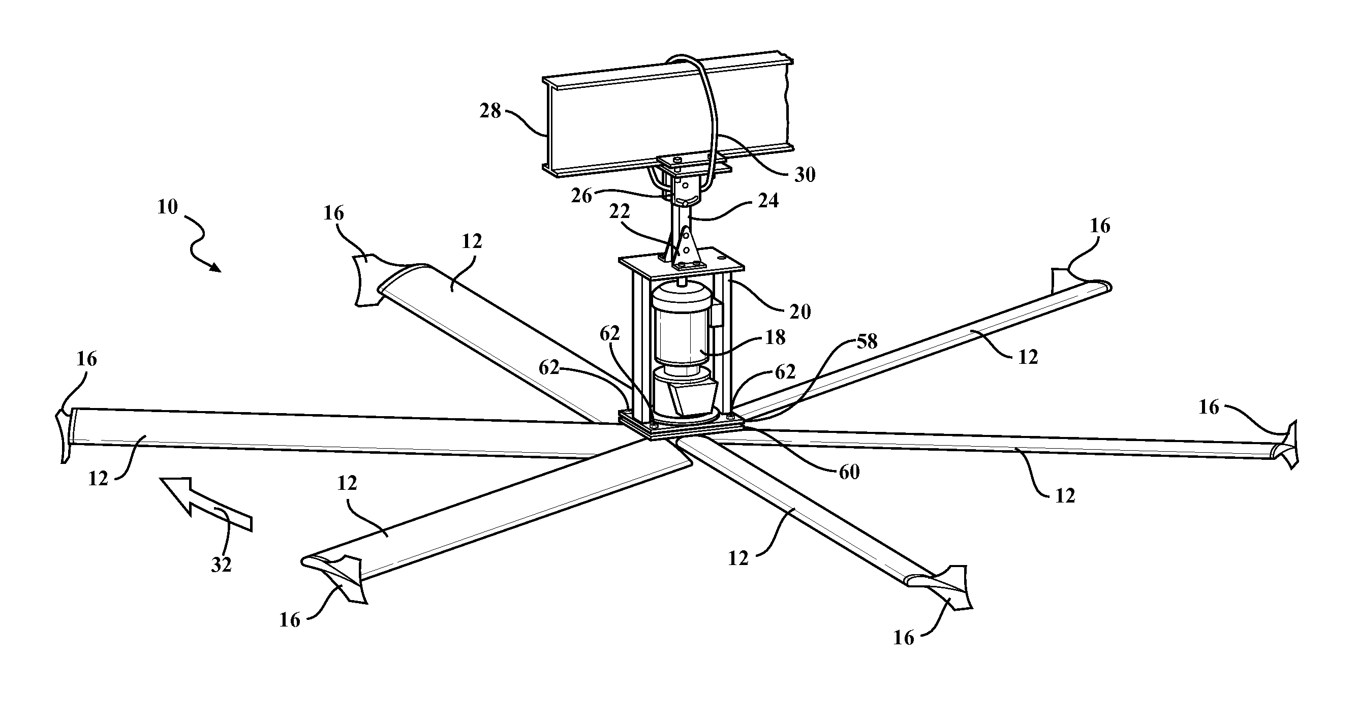
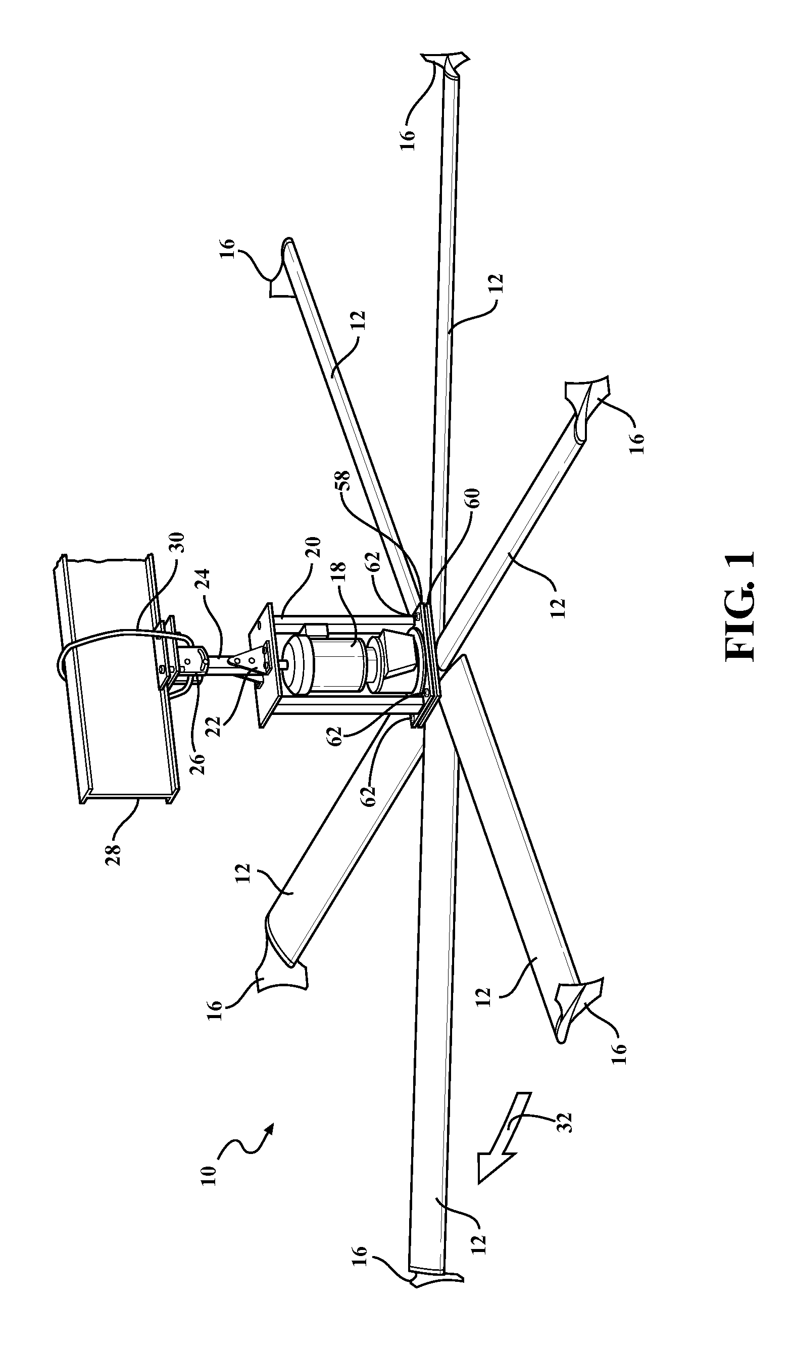
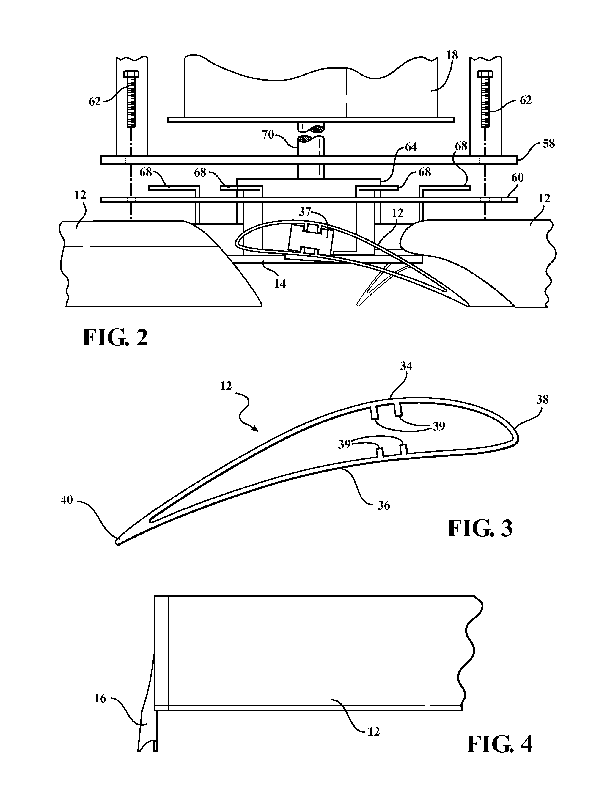
[0029]Referring to FIGS. 1-13, an HVLS fan system 10 of the disclosure includes airfoils 12 coupled at one end to a central hub 14 and extending in the other direction to a distal end having a wingtip fence 16. The central hub 14 is coupled to a motor 18 for rotating the airfoils 12. The motor 18 is connected to a frame 20 which is coupled to a lower yoke 22 and an extension bar 24 which in turn is coupled to an upper yoke 26. The upper yoke 26 is illustrated as connected to a building member 28 such as a girder or other similar structures suitable for bearing the weight of the HVLS fan system. The extension bar 24 as a backup secures the HVLS fan system to the build...


PUM


Abstract

An HVLS fan system uses STOL technology for airfoils and angle of attack thus optimizing air movement efficiency and reducing drag. The HVLS fan system includes wingtip fence end caps to the airfoils for improving efficiency by reducing drag. The HVLS fan system also includes an interconnection of the airfoils to a securing plate thus providing a failsafe and reduced potential for damage or injury resulting from failure of the connection between the airfoil array and a drive unit such as an electric motor and associated gearing.

Description

CROSS-REFERENCE TO RELATED APPLICATIONS[0001]This application claims priority to two provisional patent Applications Nos. 61 / 661,619 and 61 / 661,622 filed on Jun. 19, 2012. The disclosure of the prior applications are incorporated herein by reference.TECHNICAL FIELD[0002]The invention generally relates to high volume low speed (HVLS) fans, and more specifically HVLS fans utilizing short take off and landing (STOL) technology.BACKGROUND OF THE INVENTION[0003]Interior climate control and air circulation is difficult in certain applications, particularly including large open structural areas such as found in a factory or warehouse setting. This difficulty is encountered in both hot and cold seasonal conditions, where heat during cold weather heating migrates towards the ceiling of a building and humidity tends to migrate down during hot and humid weather conditions. Therefore, there is an interest in forcing air from the ceiling, down, towards an occupied main floor during cooler weathe...

Claims


Application Information

Patent Timeline
Patent Type & Authority Patents(United States)
IPC IPC(8): F04D29/34F01D5/14F04D25/08F04D29/38
CPCF01D5/141F04D25/088F04D29/34F04D29/384F05D2240/307
Inventor WORTMAN, JOHN D.JONES, JONATHON M.RUSSELL, IVAN
Owner SKYBLADE FAN
Why Eureka
Try Eureka