Multilayer core golf ball having hardness gradient within and between each core layer

a golf ball and multi-layer technology, applied in the field of golf balls, can solve the problems of low spin rate, general difficulty in manufacturing of golf balls, and low spin rate of two-piece golf balls, and achieve the effect of reducing or eliminating the increase in manufacturing costs and difficulty, and maximizing the benefits

Active Publication Date: 2012-11-20
ACUSHNET CO
View PDF44 Cites 39 Cited by
  • Summary
  • Abstract
  • Description
  • Claims
  • Application Information

AI Technical Summary

Benefits of technology

[0037]It is preferred that the golf ball of the present invention comprise two core layers and a cover in order to maximize the benefits achieved from such a golf ball construction—namely reducing or eliminating the increased manufacturing costs and difficulty which often result when the properties of inner core layers are undesirably altered or deteriorated as outer core layers are cured or otherwise mounted or formed around the inner core layer by applying heat. However, it is recognized and envisioned that the inventive golf ball may comprise and extend to any number of core layers, intermediate layers, and / or cover layers having regions of varying hardness within and between each layer.

Problems solved by technology

However, wound balls are generally difficult to manufacture when compared to solid golf balls.
The stiffness and rigidity that provide the durability and improved distance, however, also produce a relatively low spin rate in these two piece golf balls.
Low spin rates make golf balls difficult to control, especially on shorter shots such as approach shots to greens.
Higher spin rates, although allowing a more skilled player to maximize control of the golf ball on the short approach shots, adversely affect driving distance for less skilled players.
For example, slicing and hooking the ball are constant obstacles for the lower skill level players.
Slicing and hooking result when an unintentional side spin is imparted on the ball as a result of not striking the ball squarely with the face of the golf club.
In addition to limiting the distance that the golf ball will travel, unintentional side spin reduces a player's control over the ball.
However, the addition of fillers may adversely interfere with the resiliency of the polymers used in golf balls and thereby the coefficient of restitution of the golf balls.
However, since golf balls having hard cores and soft covers provide the most spin, the distribution taught by this patent would result in maximum core hardness at the interface when hit by a driver.
Therein the ball has a relatively high driver spin rate and not very good distance.
However, none of these references discloses a multi-layered core golf ball wherein each core layer has a plurality of hardnesses and a hardness gradient (positive, negative or a combination) within each respective core layer in addition to a hardness gradient as between core layers.

Method used


Image

  • Multilayer core golf ball having hardness gradient within and between each core layer
  • Multilayer core golf ball having hardness gradient within and between each core layer
  • Multilayer core golf ball having hardness gradient within and between each core layer

Examples


Embodiment Construction

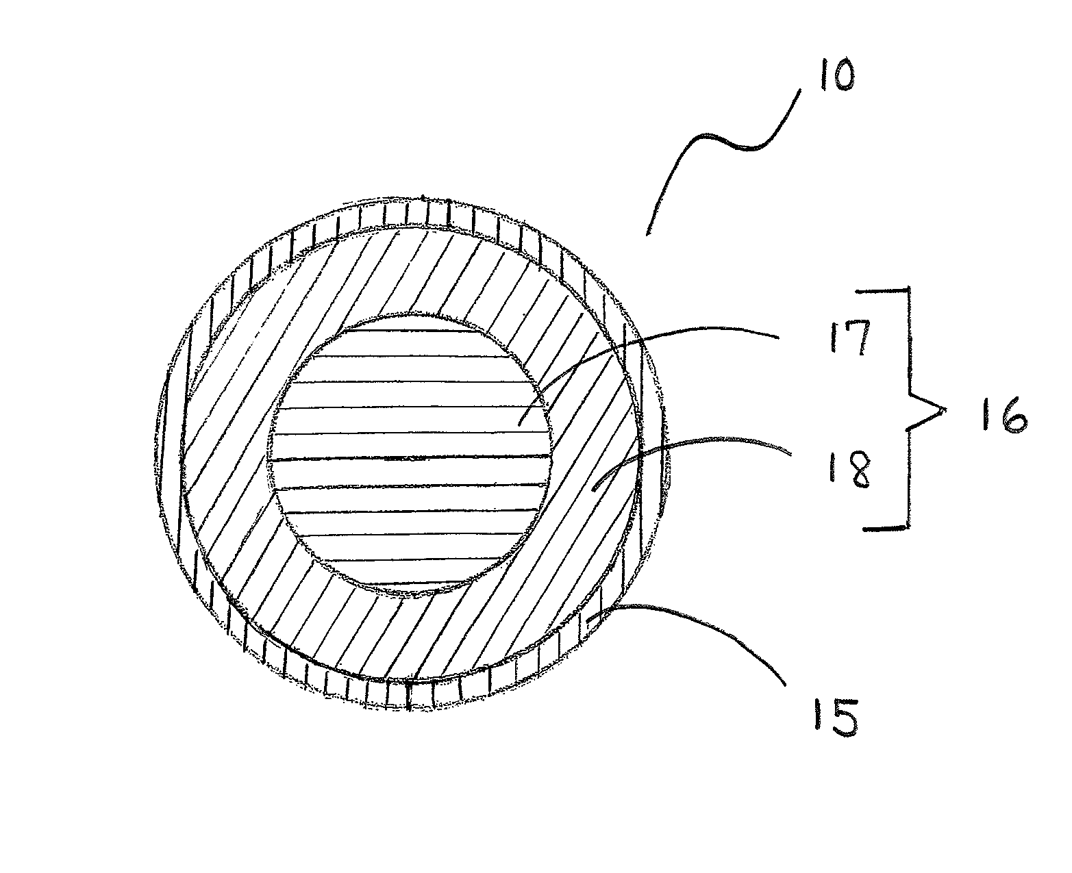
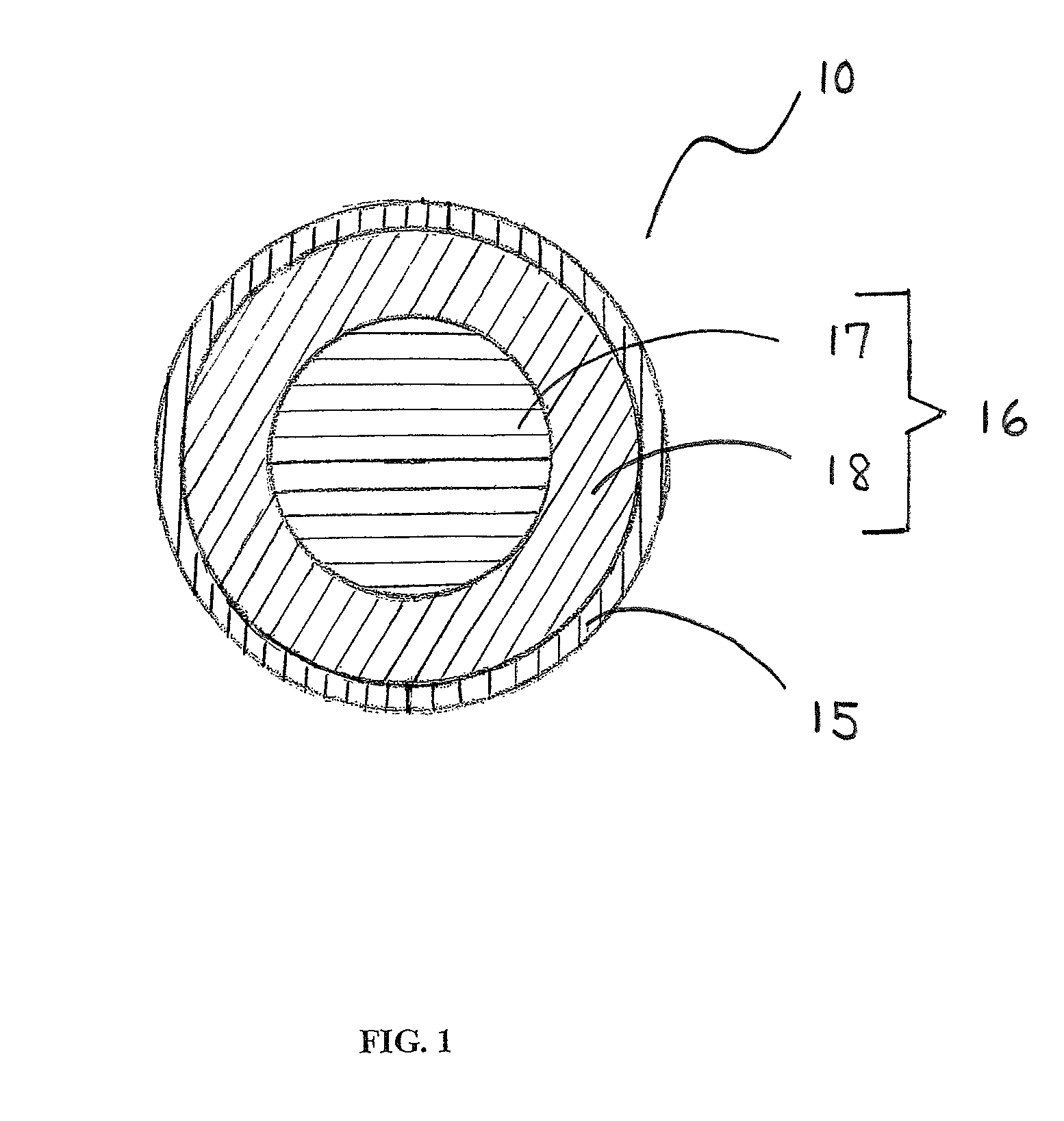
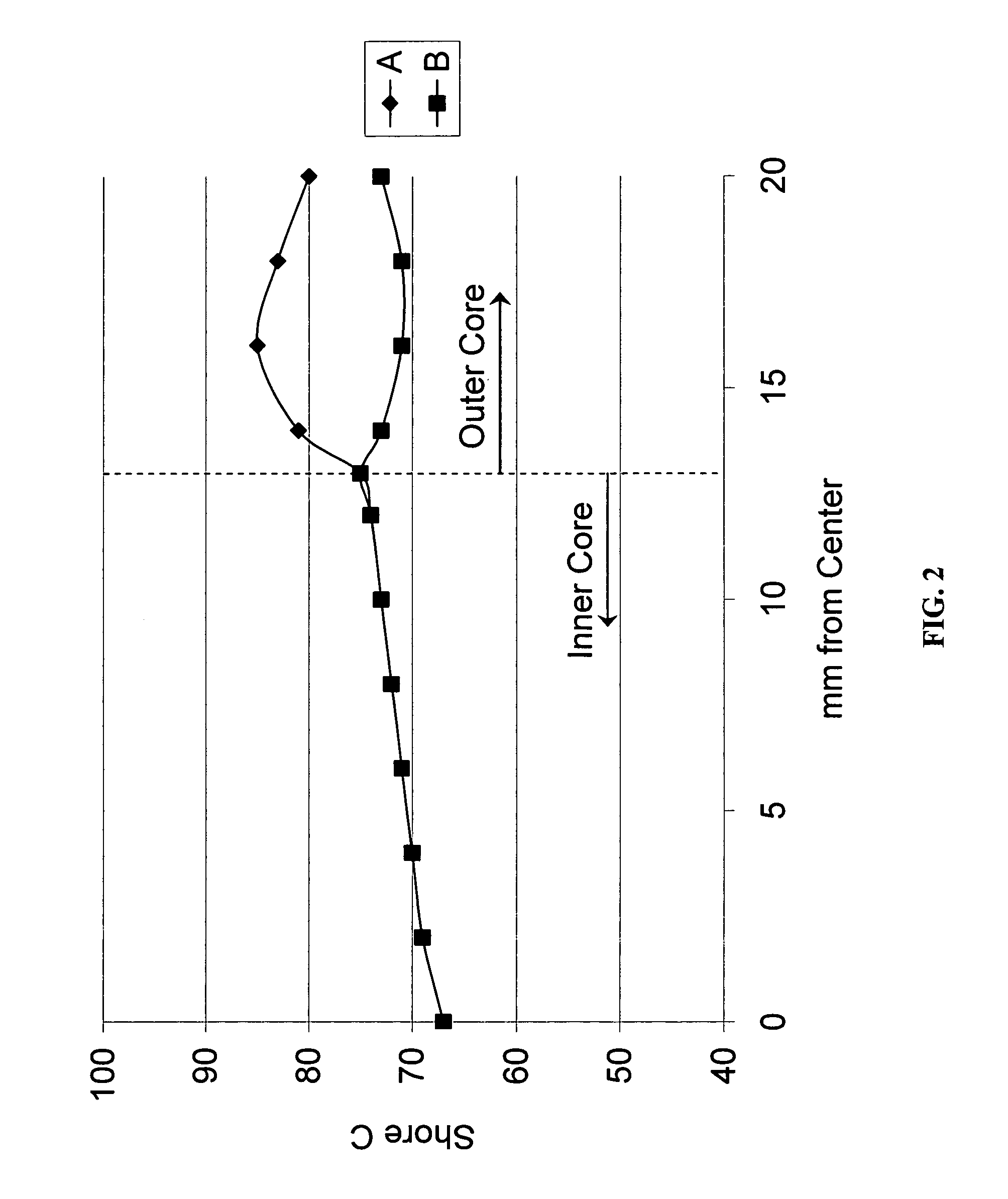
[0042]As briefly discussed above, each inventive core layer may have a hardness gradient defined by hardness measurements made at the surface of the inner core (or outer core layer) and radially inward toward the center of the inner core, typically at 2-mm increments. As used herein, the terms “negative” and “positive” refer to the result of subtracting the hardness value at the innermost portion of the component being measured from the hardness value at the outer surface of the component being measured. For example, if the outer surface of a core layer has a greater hardness value than its innermost surface, the hardness gradient will be deemed a “positive” gradient. Alternatively, if the inner surface of one layer of a multi-layer core has a greater hardness value than its inner surface, the hardness gradient for that core layer will be deemed a “negative” gradient.

[0043]Each region of a core layer (inner core region, or outer core region or inter mediate core region) may be made ...


PUM

PropertyMeasurementUnit
diameteraaaaaaaaaa
thicknessaaaaaaaaaa
diameteraaaaaaaaaa

Abstract

The present invention is directed to an improved multi-layered core golf ball wherein each core layer comprises its own specific hardness gradient (positive, negative or a combination) in addition to an overall specific hardness gradient from one core layer to the next.

Description

CROSS REFERENCE TO RELATED APPLICATIONS[0001]This application is a continuation-in-part of U.S. patent application Ser. No. 12 / 635,064, filed Dec. 10, 2009, which is a continuation-in-part of U.S. patent application Ser. No. 12 / 635,025, filed Dec. 10, 2009, which is related to other applications as follows: a continuation-in-part of U.S. patent application Ser. No. 12 / 469,312, filed May 20, 2009 now U.S. Pat. No. 7,998,002, which is a continuation-in-part of U.S. patent application Ser. No. 12 / 469,258, also filed May 20, 2009 now U.S. Pat. No. 7,963,863, which is a continuation-in-part of U.S. patent application Ser. No. 11 / 829,461, filed Jul. 27, 2007, now U.S. Pat. No. 7,537,530, which is a continuation-in-part of U.S. patent application Ser. No. 11 / 772,903, filed Jul. 3, 2007, now U.S. Pat. No. 7,537,529; further a continuation-in-part of U.S. patent application Ser. No. 12 / 492,514, filed Jun. 26, 2009 now U.S. Pat. No. 8,025,594, which is a continuation-in-part of U.S. patent ap...

Claims


Application Information

Patent Timeline
Patent Type & Authority Patents(United States)
IPC IPC(8): A63B37/06
CPCA63B37/0062A63B37/0063A63B37/0092A63B37/0064A63B37/0075A63B37/0076A63B37/00622
Inventor SULLIVAN, MICHAEL J.COMEAU, BRIANGOGUEN, DOUGLAS S.BULPETT, DAVID A.
Owner ACUSHNET CO
Why Eureka
Try Eureka