Joint prostheses and components thereof

a joint replacement and joint technology, applied in the field of joint replacement systems, kits and methods, can solve the problems of mechanical properties and adhesive properties of bone cement degrade, adversely affecting the goal of satisfactorily restoring clinical bio-mechanics, and affecting the ability to perform joint replacemen

Inactive Publication Date: 2006-05-16
OMNILIFE SCI INC
View PDF54 Cites 46 Cited by
  • Summary
  • Abstract
  • Description
  • Claims
  • Application Information

AI Technical Summary

Benefits of technology

[0018]Accordingly, it is an object of the invention to provide a component designed to be used either without cement in which the device engages into the cortical bone of the medullary canal to achieve the locking for fixation of the stem, or in a cemented application in which spacing elements are utilized to locate and a...

Problems solved by technology

Improper placement or positioning of the device can adversely affect the goal of satisfactorily restoring the clinical bio-mechanics of the joint as well as impairing adequate fixation of the component when implanted within the medullary canal of the bone.
While this method of fixation by cement provides immediate fixation and resistance to the forces encountered, and allows the surgeon to effectively position the device before the cement sets, it is not without problems.
Over time the mechanical properties and the adhesive properties of the bone cement degrade; eventually the forces overcome the cement and cause the components to become loose due to a failure at the cement/bone or cement/stem interface.
A shortfall of this approach is that, in contrast to components that utilize cement fixation, surfaces designed for biological ingrowth do not provide for immediate fixation of the stem because it takes time for the bone to grow into the specially prepared surface.
A problem with this approach is that once the flutes engage, the rotational alignment of the device is determined.
Additionally, due to the curvature of the femur, the device being inserted tends to follow the curvature as one inserts it, which can cause the device to rotate into a less desirable position.
However, it is desirable for movement to be minimized during the cement curing stage as stem movements in the curing cement will almost certainly negatively affect stem-cement attachment.
Another problem with prostheses designed for press-fit and/or bone ingrowth fixation is that, in order to achieve adequate stability, the device must make direct contact with cortical bone in the diaphysis, rather than having a layer of intervening bone cement with a lower elastic modulus than that of the stemmed portion of the device.
These slots, however, decrease the strength of the stem relative to a stem with no slot, especially for l...

Method used


Image

  • Joint prostheses and components thereof
  • Joint prostheses and components thereof
  • Joint prostheses and components thereof

Examples


Embodiment Construction

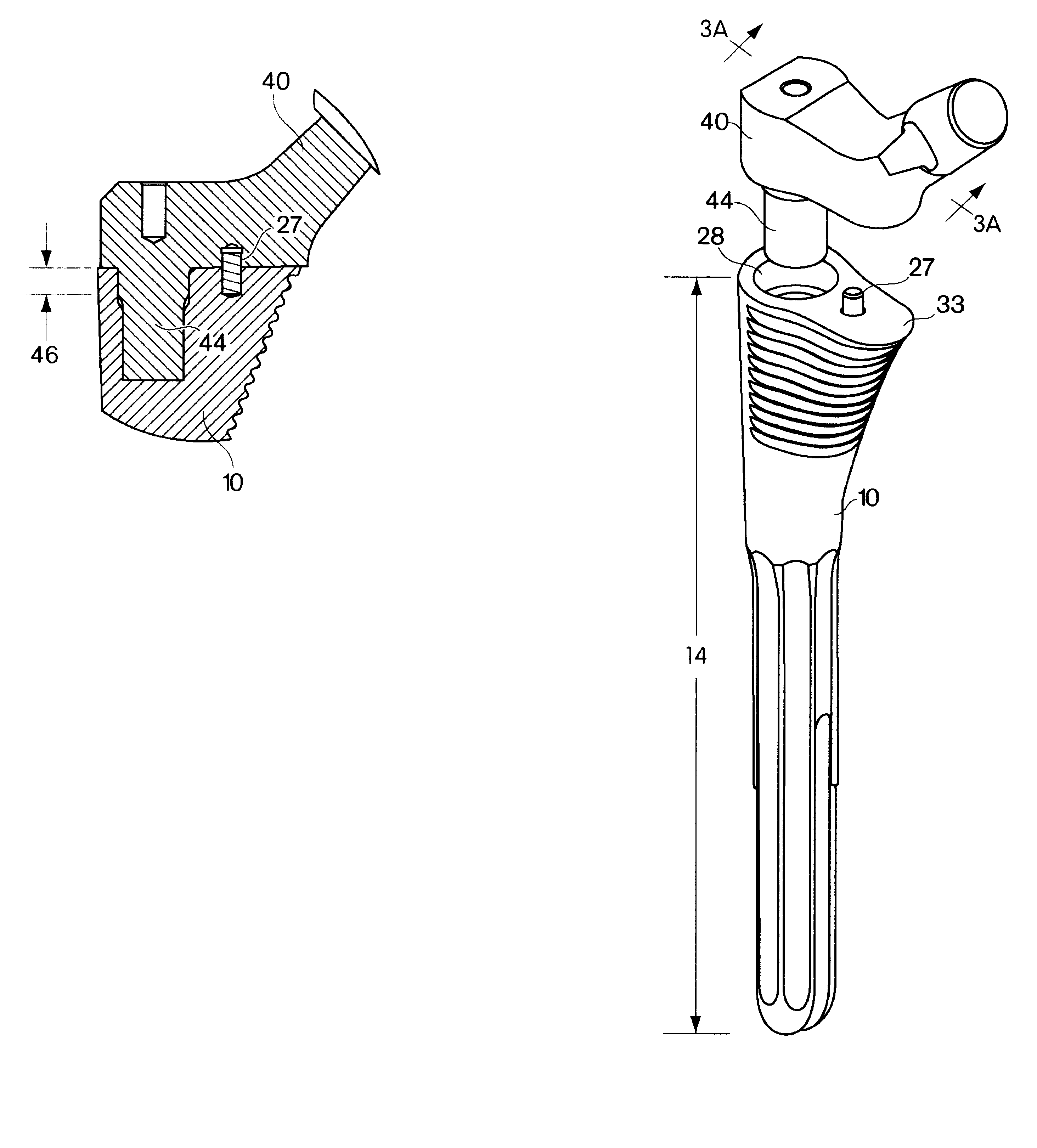
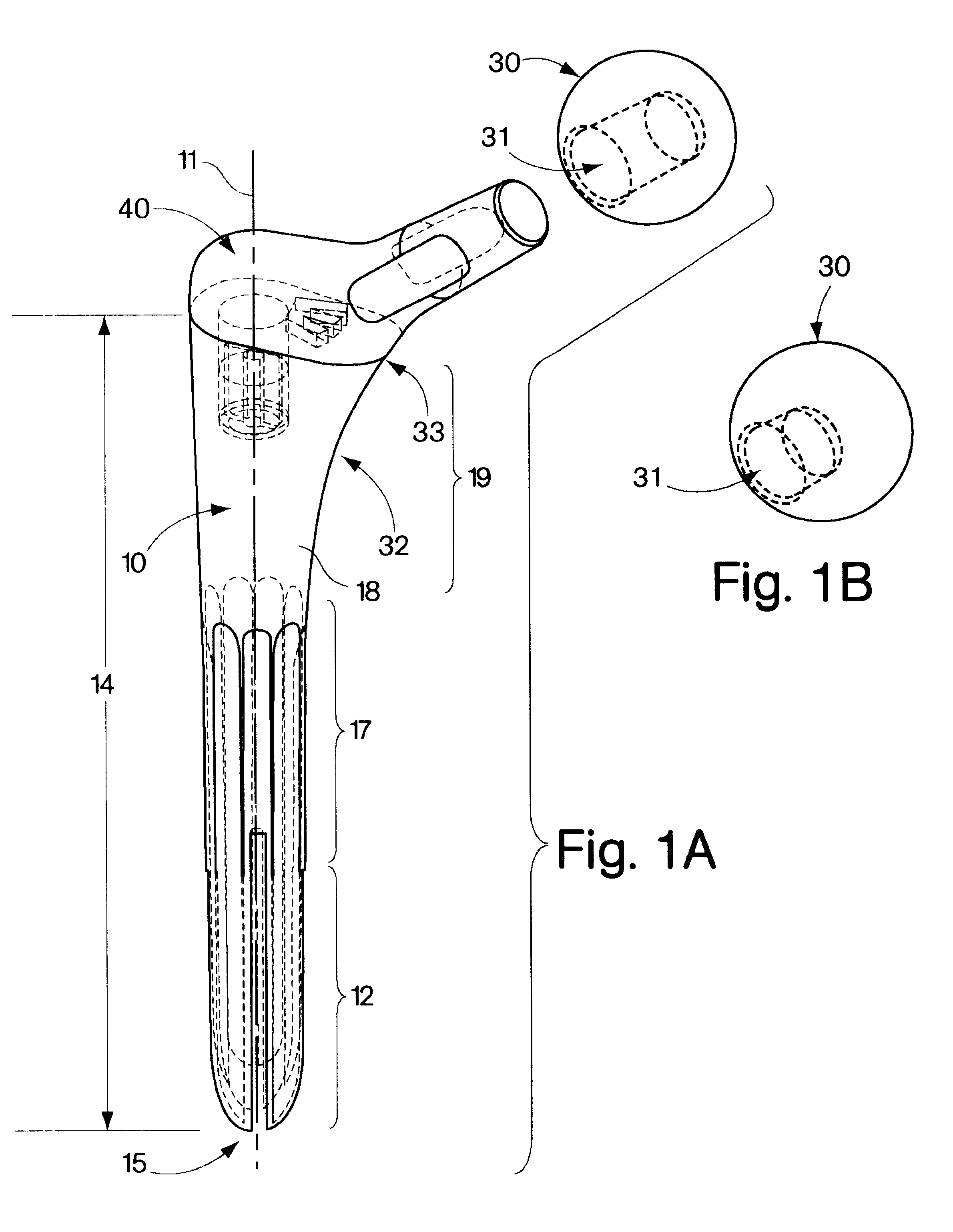
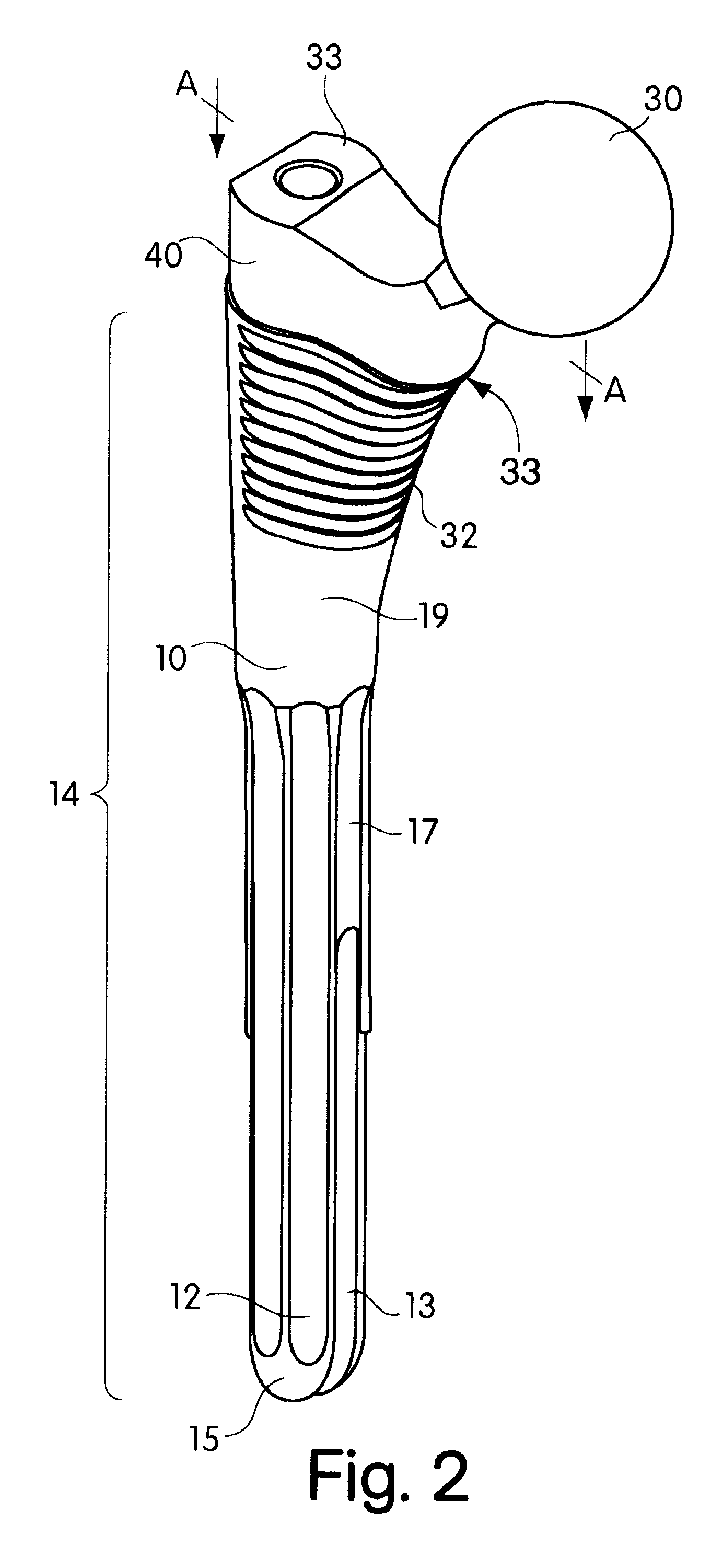
[0046]The present invention is suitable for replacement of any joint comprising a bone shaft, a joint head bearing articular cartilage and in anatomic continuity with the bone shaft, and a joint socket bearing articular cartilage that receives the joint head and permits motion of the joint head and the bone shaft relative to the joint socket. Examples of joints where a single rounded joint head may be found articulating with a cupped joint socket include the hip, the glenoid, the metacarpophalangeal joints and the metatarsophalangeal joints. The present invention is well adapted for prosthetic replacement of these joints. The systems, kits and methods of the present invention may also be adapted for use in joints wherein the joint head comprises two condyles, as in the knee or the interphalangeal joints, or in joints such as the radial elbow joint where a single humeral condyle acts as a joint head articulating with a joint socket on the radial head. In providing a prosthesis accord...


PUM


Abstract

Modular joint prostheses and components thereof are disclosed. In an embodiment, a joint prosthesis may include a head member, a neck member, and a stem member.

Description

CROSS REFERENCE TO RELATED APPLICATIONS[0001]This application is a continuation of U.S. Ser. No. 09 / 583,805, filed May 30, 2000 now U.S. Pat. No. 6,702,854, which claims benefit of U.S. Provisional Application Ser. No. 60 / 136,815, filed Jun. 1, 1999, and of U.S. Provisional Application Ser. No. 60 / 168,526, filed Dec. 2, 1999. All of the above-listed applications are hereby incorporated herein by reference in their entireties.BACKGROUND OF INVENTION[0002]1. Field of the Invention[0003]The present invention relates generally to systems, kits and methods for joint replacement using multiple components. In one embodiment, the present invention includes as components a head, a neck and a stem.[0004]2. Related Art[0005]Artificial joint prostheses are widely used today, restoring joint mobility to patients affected by a variety of conditions, including congenital, degenerative, iatrogenic and traumatic afflictions of the joints. The satisfactory performance of these devices can be affected...

Claims


Application Information

Patent Timeline
IPC IPC(8): A61F2/32A61F2/36
CPCA61F2/36A61F2230/005A61F2/38A61F2/40A61F2/42A61F2002/30171A61F2002/30331A61F2002/3038A61F2002/30484A61F2002/30604A61F2002/30616A61F2002/30797A61F2002/30881A61F2002/3639A61F2002/3652A61F2002/3656A61F2002/3668A61F2002/3696A61F2002/4619A61F2002/4641A61F2220/0025A61F2220/0033A61F2/3672A61F2002/3054A61F2002/30594A61F2002/30884A61F2002/3631
Inventor CHEAL, EDWARD J.CIPOLLETTI, GEORGE B
Owner OMNILIFE SCI INC
Why Eureka
Try Eureka