
Zero-Backlash Bushing

a bushing and zero backlash technology, applied in the direction of screw, threaded fastener, load modified fastener, etc., can solve the problems of exposing the bushing-screw assembly to backlash, deviation from their proper positions and/or alignments, etc., to prevent the lateral migration of grease out of the bushing, and prevent the effect of radial pressure on the greas

Inactive Publication Date: 2014-10-09
KOZAK EUGENIUSZ
View PDF13 Cites 3 Cited by
  • Summary
  • Abstract
  • Description
  • Claims
  • Application Information

AI Technical Summary

Benefits of technology

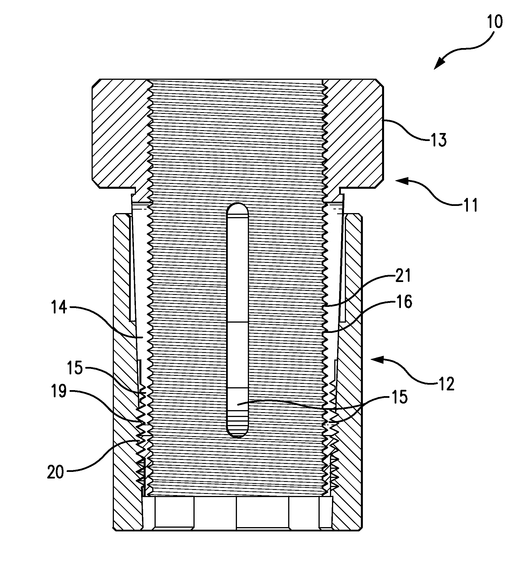
The present invention relates to a design for a bushing assembly to prevent the lateral migration of grease. The design features two design features: a central section of the internal threading of the bushing core with truncated V-threads and the external sharp V-offs of the screw, which isolates the radial gaps as circulation channels and prevents grease from migrating out of the bushing. Additionally, the patent text describes how the axial compression of the bushing core against the adjustment screw is increased by the tightness of the engagement between the outer threading of the bushing core and the internal threading of the annular sleeve, resulting in a secure lock and prevention of backlash. The patent also mentions the use of an O-ring and other features to prevent the bushing sleeve from loosening or over-tightening.

Problems solved by technology

Backlash is a phenomenon that occurs when mechanical components are subjected to pressure and / or vibration, causing them to deviate from their proper positions and / or alignments.
Nonetheless, the forward-biased thread engagement induced by the locking nut leaves rearward lateral gaps between the engaged threads, which lateral gaps can enable rearward backlash movement of the screw when it is subjected to a load.
But the rearward pressure of the loaded screw will, over time, force the grease to flow out of the lateral inter-thread gaps and through the front of the bushing, thereby exposing the bushing-screw assembly to backlash.

Method used


Image

  • Zero-Backlash Bushing
  • Zero-Backlash Bushing
  • Zero-Backlash Bushing

Examples


Embodiment Construction

[0031]The present invention has two preferred embodiments. The second preferred embodiment differs from the first preferred embodiment insofar as the second includes the locking O-ring feature.

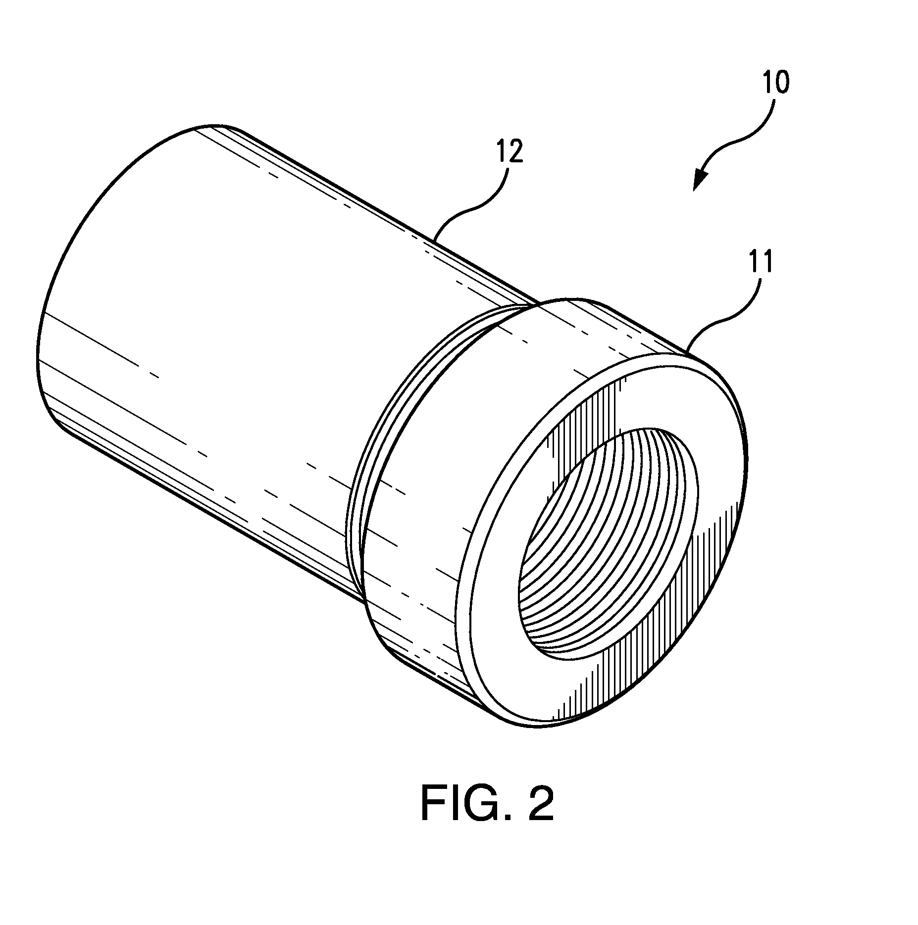
[0032]Referring to FIGS. 2-4, a composite bushing 10 according to the preferred embodiments of the present invention comprises bushing core 11 and a bushing sleeve 12. As shown in FIG. 6, the core bushing 11 has a broad annular head section 13 and a narrower tapered shaft 14. While the head section 13 of the bushing core 11 is rigid, the shaft 14 is flexibly resilient, so that its circumference constricts when subjected to sufficient radial pressure and expands again to its original form upon the release of such pressure. The constriction and expansion of the bushing core 11 is facilitated by three longitudinally-oriented oblong core slots 15 in the core's shaft 14.

[0033]As depicted in FIGS. 5A-B, 7A-B and 8A-B, the bushing core 11 has, along the entire length of its axial bore, core internal ...


PUM


Abstract

A zero-backlash bushing employs a dual-component composite design, comprising a tapered resilient slotted bushing core compressibly engaged by a cylindrical annular sleeve. As opposed to the axial pressure of a locking nut, the annular sleeve exerts a circumferential pressure on the bushing core, thereby inducing a tight radial engagement between the threads of the bushing core and the adjustment screw, as opposed to the lateral thread engagement induced by a locking nut. This tight radial engagement leaves radial gaps between the threads of the bushing core and the screw, which radial gaps can be filled with grease. Slots in the bushing core enable migration of grease within the bushing and facilitate constriction of the bushing core.

Description

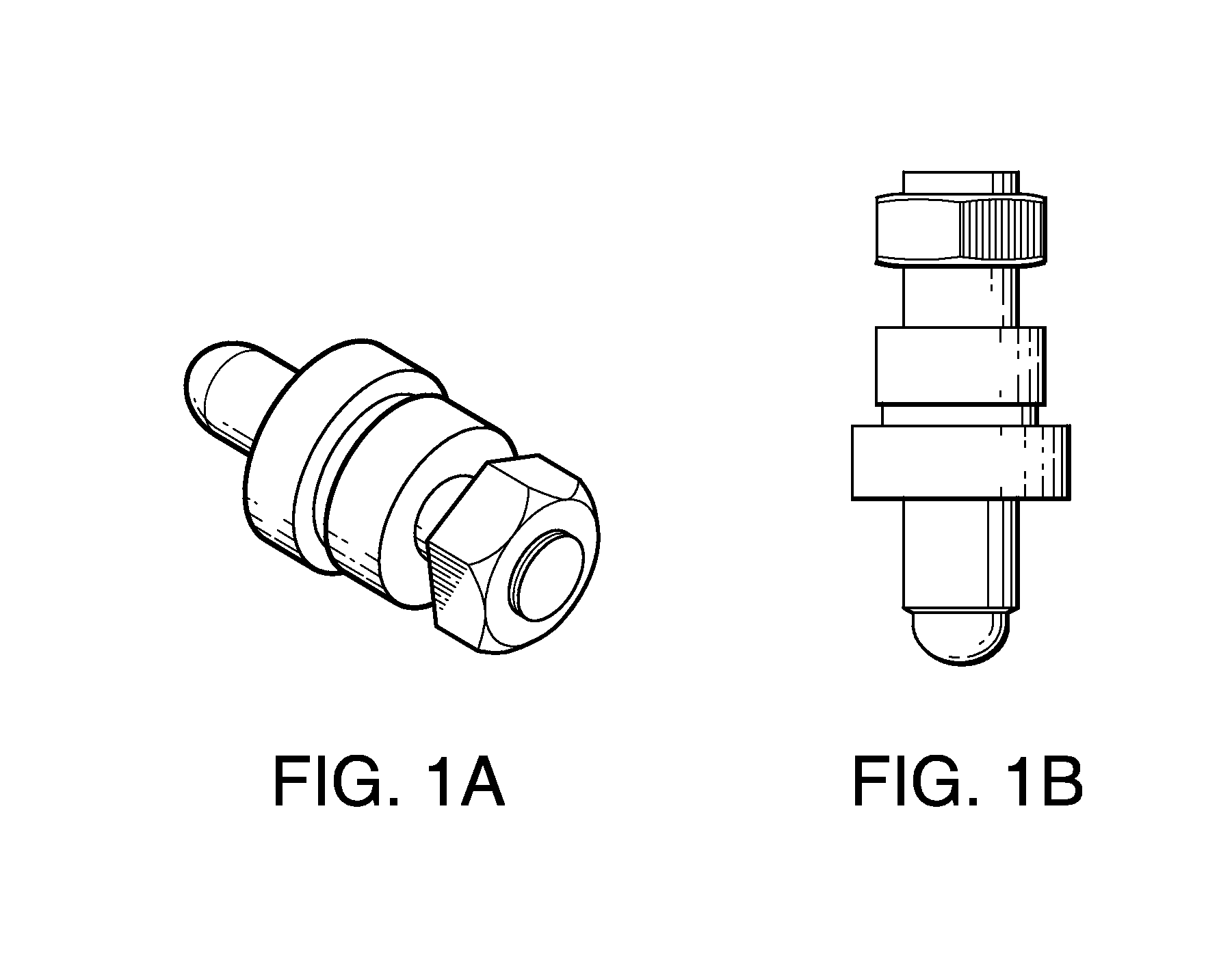
BACKGROUND OF THE INVENTION[0001]The present invention relates to field of bushing assemblies that are matched with fine and ultra-fine adjustment screws of the type used in the alignment of optical components, such as mirror mounts and lasers. More particularly, the present invention relates to bushing assemblies that reduce or eliminate backlash.[0002]Backlash is a phenomenon that occurs when mechanical components are subjected to pressure and / or vibration, causing them to deviate from their proper positions and / or alignments.[0003]In the case of bushings used in conjunction with fine / ultra-fine adjustment screws for the alignment of optical components, such as lasers, a locking nut is often used to secure the position of the bushing against misalignment. As illustrated in FIGS. 1A and 1B, the tightened locking nut applies an axial pressure to the bushing which forces its threads into a tight lateral engagement with those of the adjustment screw. Nonetheless, the forward-biased th...

Claims


Application Information

Patent Timeline
Patent Type & Authority Applications(United States)
IPC IPC(8): F16B29/00
CPCF16B29/00F16B5/0233F16B19/02F16B31/02F16B39/028
Inventor KOZAK, EUGENIUSZ
Owner KOZAK EUGENIUSZ
Learn More