Image analysis

An image and score technology, applied in image analysis, image data processing, instrumentation, etc., to solve problems such as false alarms

Active Publication Date: 2008-08-20
BRITISH TELECOMM PLC
View PDF5 Cites 2 Cited by
  • Summary
  • Abstract
  • Description
  • Claims
  • Application Information

AI Technical Summary

Problems solved by technology

Curved boundaries in images that do not contain actual vanishing points can cause false alarms

Method used


Image

  • Image analysis
  • Image analysis
  • Image analysis

Examples


Embodiment Construction

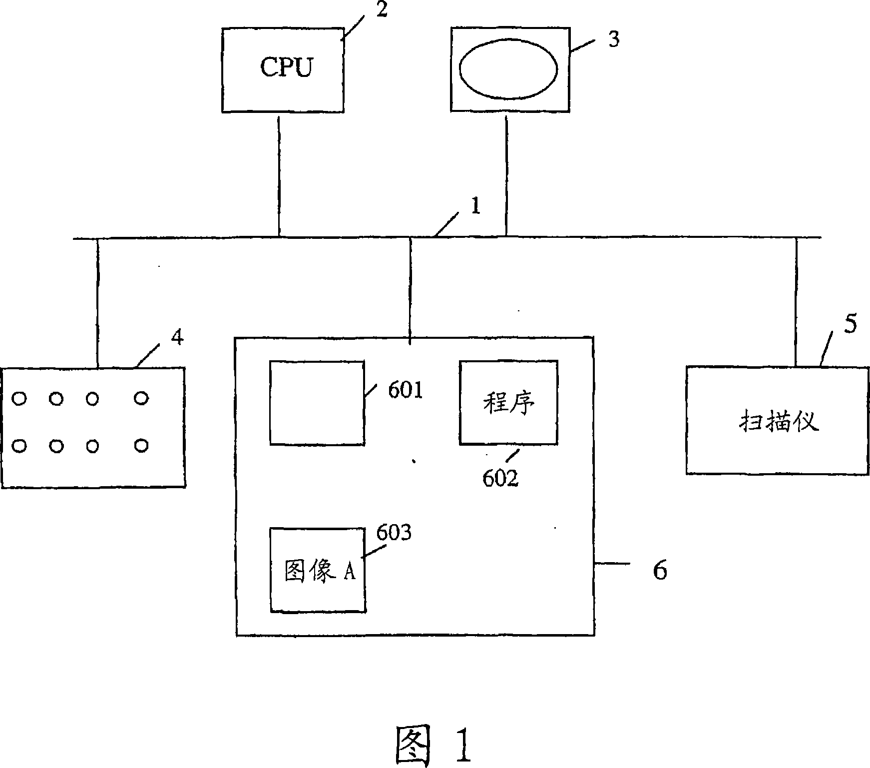
[0020] FIG. 1 shows an apparatus consisting of a general-purpose computer programmed to perform image analysis according to a first embodiment of the invention. The device has a bus 1 to which a central processing unit 2 , a visual display 3 , a keyboard 4 , a scanner 5 (or other means, not shown) for inputting images and a memory 6 are connected.

[0021] In the memory 6 are stored an operating system 601, a program 602 for performing image analysis, and a storage area 603 for storing images. Stores an image as a two-dimensional array of values, each representing the brightness and / or color components of a picture element within the array.

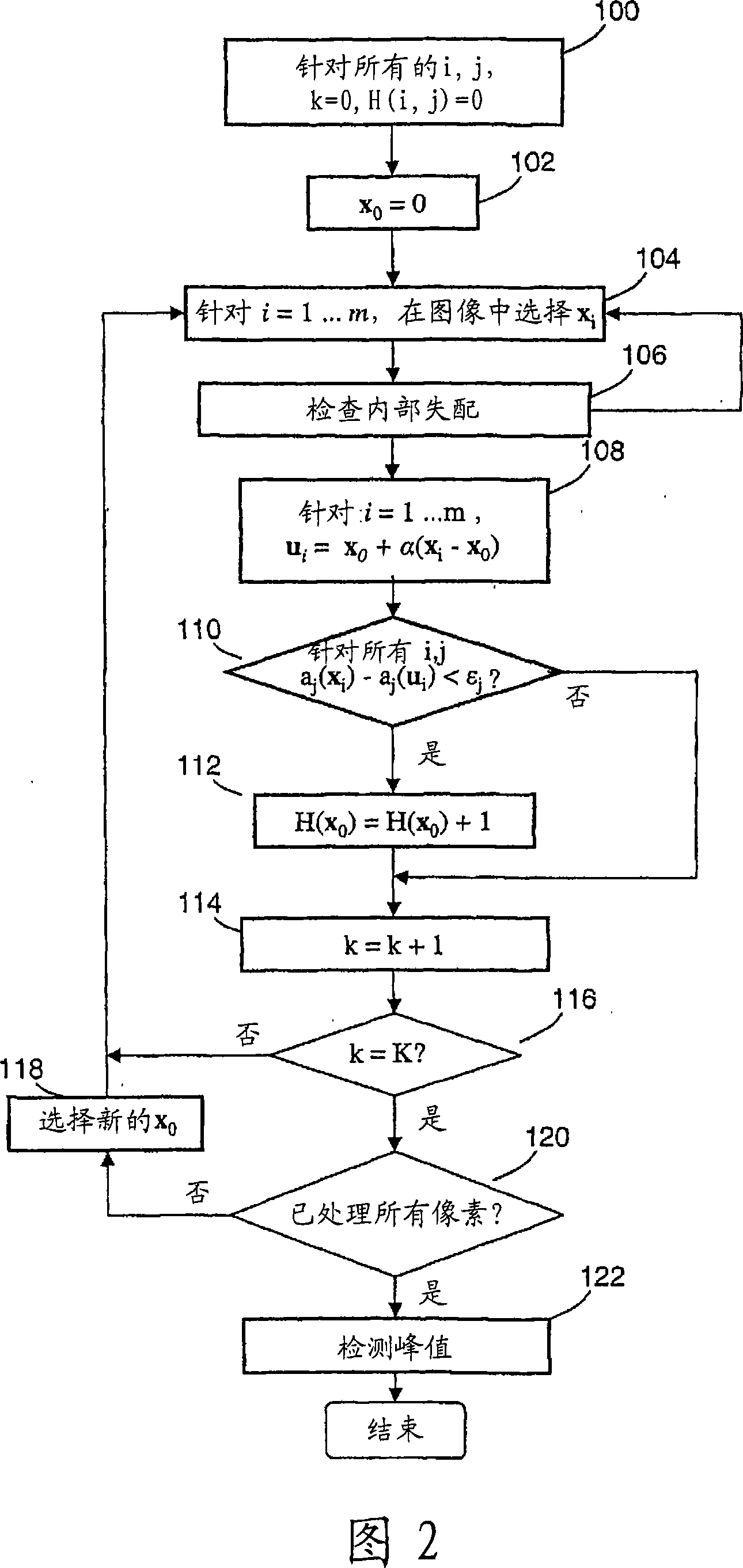
[0022] The image array consists of picture elements x i ‾ = ( x i , y i ) An array of , where x i and y i is the horizontal ...


PUM


Abstract

The present invention relates to image analysis. An image represented by an ordered set of elements (xi) each having a value is analyzed to detect vanishing points. The method comprises repeating for each of a plurality of root positions (x0): (i) selecting a first plurality of elements (xi) from said ordered set; (ii) for each selected element ( xi), select the second element (ui) such that the vector position of the selected second element relative to the root position is scaled by a factor (α) compared to the position of the first selected element; (iii) determine the selected whether the element satisfies a matching criterion that requires the value of each of the plurality of first elements to be similar to the value of the corresponding second element; and (iv) in the case of a match, updating the similarity score with respect to the root element (H). Once these scores are found, they can be examined for the part of the image corresponding to the peak of the similarity score.

Description

technical field [0001] The present invention relates to image analysis, and more particularly to extracting three-dimensional information from two-dimensional images. Background technique [0002] Perspective is present to some degree in all images that reflect 3D information. Parallel lines in a 3D scene are projected to a vanishing point in the image. Localizing vanishing points provides a powerful way to infer 3D structure from 2D images, especially in landscapes or man-made environments. Lutton et al. [1] extract edges and set line segments pointing to vanishing points. This method requires knowledge of camera parameters and has to deal with a large number of very short line segments generated from a particular image. McLean et al. [2] clustered gradient orientations to again detect line structures in images and evaluated the method on two grayscale images. Together with other authors, Shufelt [3] used a Gaussian sphere representation and worked on solving the proble...

Claims


Application Information

Patent Timeline
Patent Type & Authority Applications(China)
IPC IPC(8): G06T7/00G06V10/44G06V20/00
CPCG06K9/4604G06K9/00624G06T7/00G06V20/00G06V10/44
Inventor 弗雷德里克·沃里克·迈克·斯腾蒂福特
Owner BRITISH TELECOMM PLC
Why Eureka
Try Eureka