Device for holding a piston in a plant for coating pistons

A technology for fixing devices and coating equipment, which is applied in the direction of surface coating liquid devices, workpiece clamping devices, coatings, etc., and can solve the problems of complicated and laborious manufacturing of piston fixing devices

Inactive Publication Date: 2008-09-03
MAHLE INT GMBH
View PDF1 Cites 4 Cited by
  • Summary
  • Abstract
  • Description
  • Claims
  • Application Information

AI Technical Summary

Problems solved by technology

The disadvantage of this method is that the described piston fixing device is complicated to produce and that the fixing of the piston to the piston fixing device is particularly labor-intensive

Method used


Image

  • Device for holding a piston in a plant for coating pistons
  • Device for holding a piston in a plant for coating pistons

Examples


Embodiment Construction

[0008] Today's engines have multiple pistons made of aluminum oxide, which can be coated with iron to reduce wear on the pistons. It is usually achieved by electrolytic coating. For this purpose, a corresponding coating system comprises a plurality of coating electrolytic cells, each of which comprises a plurality of piston holders to which the pistons are fastened.

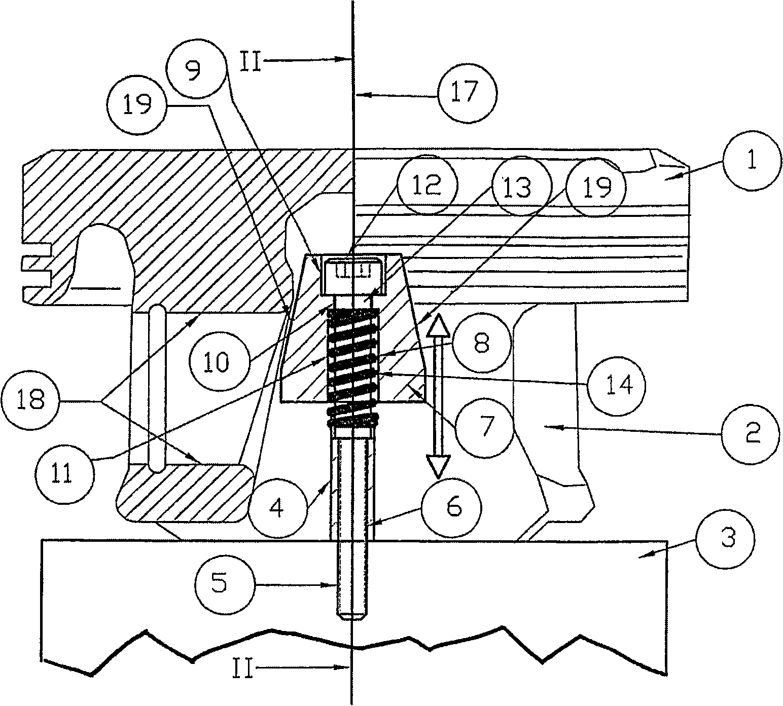
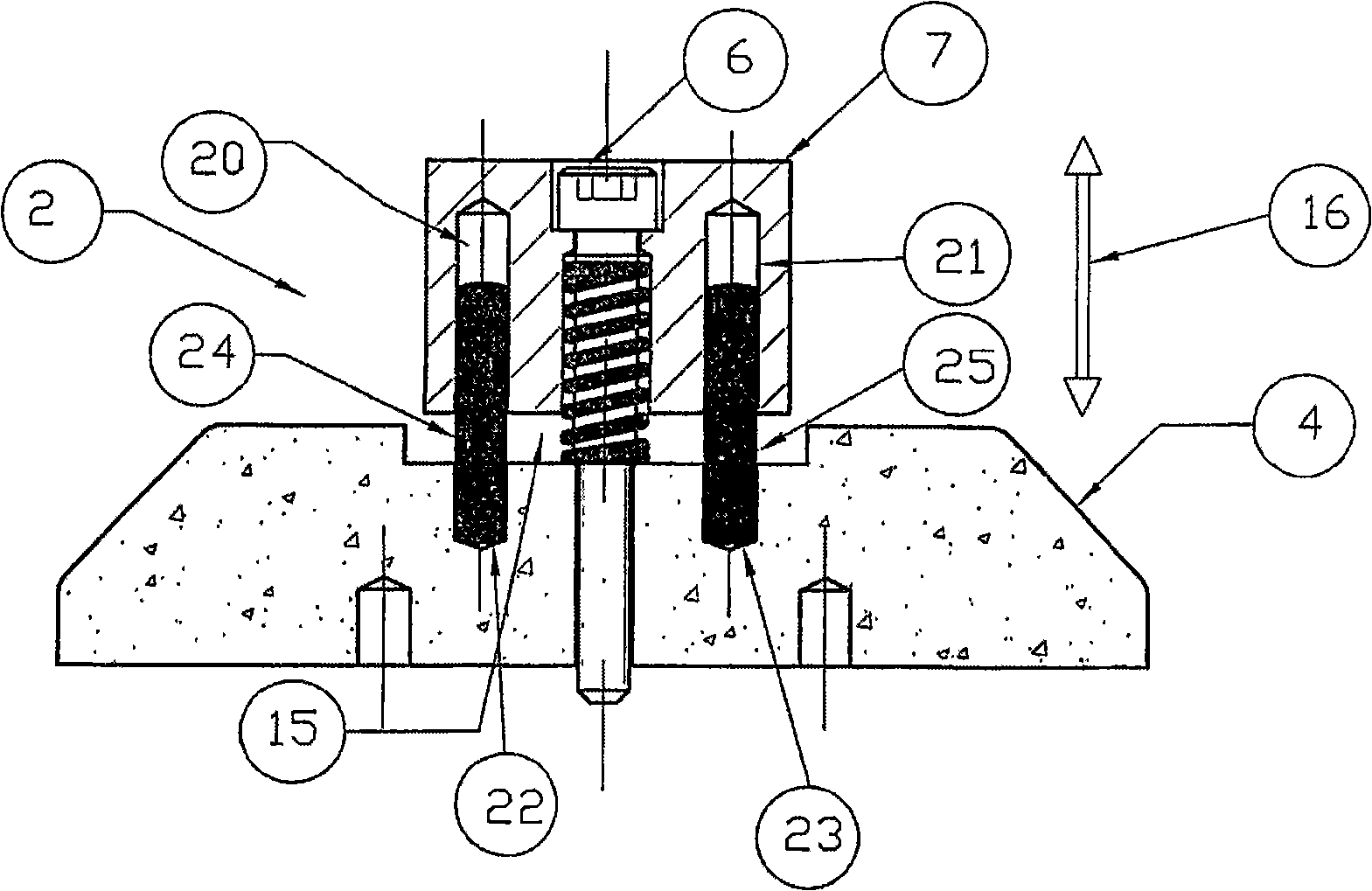
[0009] like figure 1 As shown, the fixing device 2 of the piston 1 includes a bracket 3 on which a base 4 fixed by a hexagonal screw 6 is arranged. The carrier 3 includes a threaded bore 5 with an internal thread running vertically, that is to say parallel to the axial direction 17 of the piston. A hexagonal screw 6 is screwed into this threaded hole 5 for fastening a calibration part 7 made of brass. For screwing in the screw 6 , the alignment part 7 has a through-bore 8 which is divided into three. The bore 8 consists of an upper part 9, a middle part 10 and a lower part 11 close to the bottom end of the pi...


PUM


Abstract

The invention relates to a device (2), in a plant for coating pistons, for holding a piston (1) of an internal combustion engine, comprising an aligning piece (7), which is arranged on a surface (3) of the device (2) in the direction of the axis (17) of the piston (1) in an elastically flexible manner and which comprises two opposing surfaces resting on the inner surface of the gudgeon pin boss (18) of the piston (1) conically tapering in the direction of the piston crown. A simple construction of the piston holder which permits a fault-free and even coating of the piston which can be rapidly and simply fixed to the piston is achieved.

Description

technical field [0001] The invention relates to a piston holding device in the preamble of claim 1 for use in a coating device for pistons. Background technique [0002] The US patent document with application number 5435873 discloses a piston coating device, in which the piston is fixed on a plunger type iron core arranged on the rotating shaft of the motor. The piston-shaped end and the plug-hole-shaped end of the plunger are kept at a certain distance by a compression spring, and each plunger can be inserted into the screw hole of the piston. The pistons are coated by a motor turning the pistons so that each piston enters a respective tank and attracts the plating material in the tank. The disadvantage of this method is that the described piston fixing device is complex to manufacture and that the fixing of the piston to the piston fixing device is particularly complex. Contents of the invention [0003] The object of the present invention is to avoid this disadvantag...

Claims


Application Information

Patent Timeline
Patent Type & Authority Applications(China)
IPC IPC(8): B25B11/00
CPCB25B11/00B05C3/09B05C13/025
Inventor 乔希姆·林克尔
Owner MAHLE INT GMBH
Why Eureka
Try Eureka