Refrigeration circulation device
A refrigeration cycle and refrigerant technology, which is applied to household refrigeration devices, refrigerators, refrigeration components, etc., can solve problems such as the limitation of the condensation amount of the heat exchanger used for condensation, the capacity of the refrigeration cycle device (heating capacity reduction, etc.), and achieve the reduction of suppression capacity Effect
- Summary
- Abstract
- Description
- Claims
- Application Information
AI Technical Summary
Problems solved by technology
Method used
Image

Examples
Embodiment 1
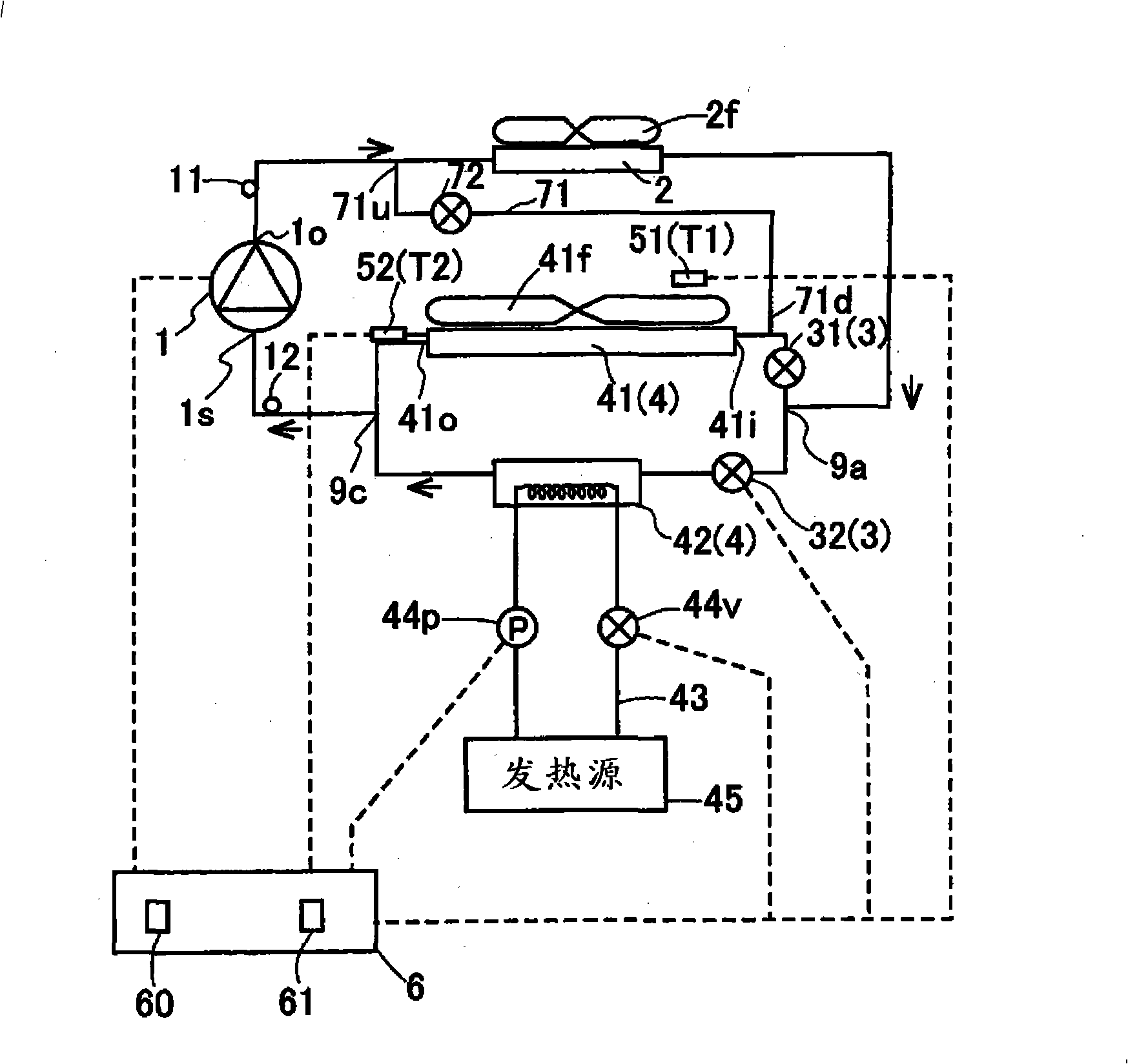
[0049] Below, refer to figure 1 Example 1 of the present invention will be described. figure 1 A system diagram showing a refrigeration cycle device (cooling cycle device). Such as figure 1 As shown, the refrigeration cycle apparatus includes: a compressor 1 for performing a compression step of compressing a gaseous refrigerant to form a high-temperature and high-pressure refrigerant; 2, an expansion valve 3 that expands the refrigerant that has passed through the condensation process to reduce its pressure, an evaporation heat exchanger 4 that performs the evaporation process of evaporating the refrigerant that has passed through the expansion valve 3, and controls the opening of the expansion valve 3 degree of control section 6. The control unit 6 has a memory 60 and a CPU 61 .
[0050] Such as figure 1 As shown, the condensation heat exchanger 2 is arranged indoors and functions as an indoor heat exchanger. The heat exchanger 2 for condensation has blower 2f, and is u...
Embodiment 2
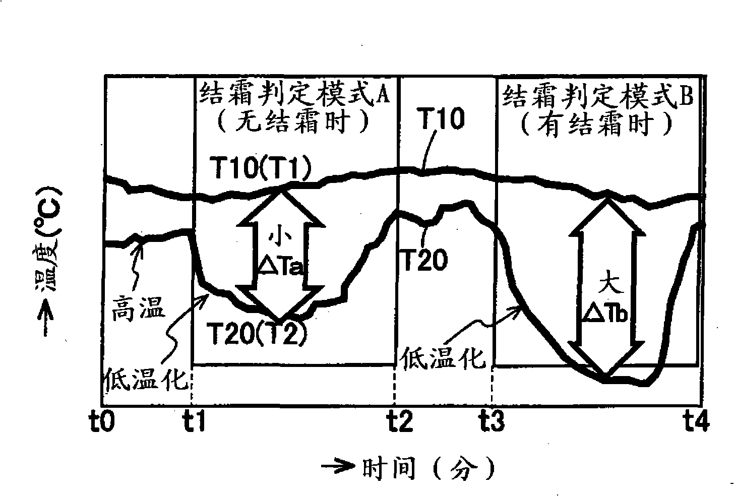
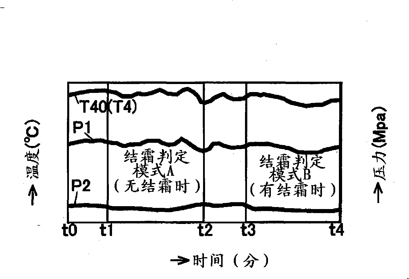
[0067] use figure 1 Example 2 will be described. This embodiment has basically the same configuration and effects as those of Embodiment 1. Hereinafter, the different parts will be mainly described. When the frost determination mode is executed and it is determined that frost has formed, the defrost mode is implemented. Hereinafter, the frost detection mode will be described. When frost is formed on the surface of the air heat exchanger 41, the heat exchange efficiency of the air heat exchanger 41 decreases, and thus the heating operation capability decreases. Therefore, the evaporation process of the refrigerant in the air heat exchanger 41 is impaired, the evaporation amount of the refrigerant is suppressed, and the pressure of the refrigerant in the air heat exchanger 41 gradually decreases. At this time, the evaporation temperature in the air heat exchanger 41 (detection temperature of the heat exchange temperature sensor 52 ) gradually decreases. Thus, the temperatur...
Embodiment 3
[0082] use figure 1 Example 3 will be described. This embodiment has basically the same configuration and effects as those of Embodiment 1. Hereinafter, the different parts will be mainly described. Figure 4 A flowchart showing the control mode A executed by the CPU 61 of the control unit 6 . Y is equivalent to yes. N is equivalent to no. Such as Figure 4 As shown, first, the control unit 6 performs the heating operation in the normal operation mode while turning on the power (step S2). The control unit 6 determines whether or not a set time β1 (for example, 30 minutes) or more has elapsed since the start of the heating operation, or whether the set time β1 has elapsed since the end of the defrosting mode, or whether it has been determined from frost formation. The mode (no frost formation) ends when the set time β1 (for example, 30 minutes) or more has elapsed (step S4). When the set time β1 has elapsed (YES in step S4), the control unit 6 implements the frost detect...
PUM
 Abstract
Description
Claims
Application Information
 - R&D
- Intellectual Property
- Life Sciences
- Materials
- Tech Scout
- Unparalleled Data Quality
- Higher Quality Content
- 60% Fewer Hallucinations
Browse by: Latest US Patents, China's latest patents, Technical Efficacy Thesaurus, Application Domain, Technology Topic, Popular Technical Reports.
© 2025 PatSnap. All rights reserved.Legal|Privacy policy|Modern Slavery Act Transparency Statement|Sitemap|About US| Contact US: help@patsnap.com