Bank note automatic teller machine

An automatic teller machine and banknote technology, which is applied to banknote processing equipment, handling coins or valuable banknotes, and devices for accepting coins, etc., and can solve problems such as large gaps and poor banknote stacking.

Inactive Publication Date: 2008-09-17
OKI ELECTRIC IND CO LTD
View PDF1 Cites 21 Cited by
  • Summary
  • Abstract
  • Description
  • Claims
  • Application Information

AI Technical Summary

Problems solved by technology

[0029] Finally, when the upper surface detection sensor 109 is turned on, the table 112 is lowered to form a space with a large gap. Problems in Fig. 20(6) such as poor stacking such as banknotes standing up in the space

Method used


Image

  • Bank note automatic teller machine
  • Bank note automatic teller machine
  • Bank note automatic teller machine

Examples


Embodiment 1

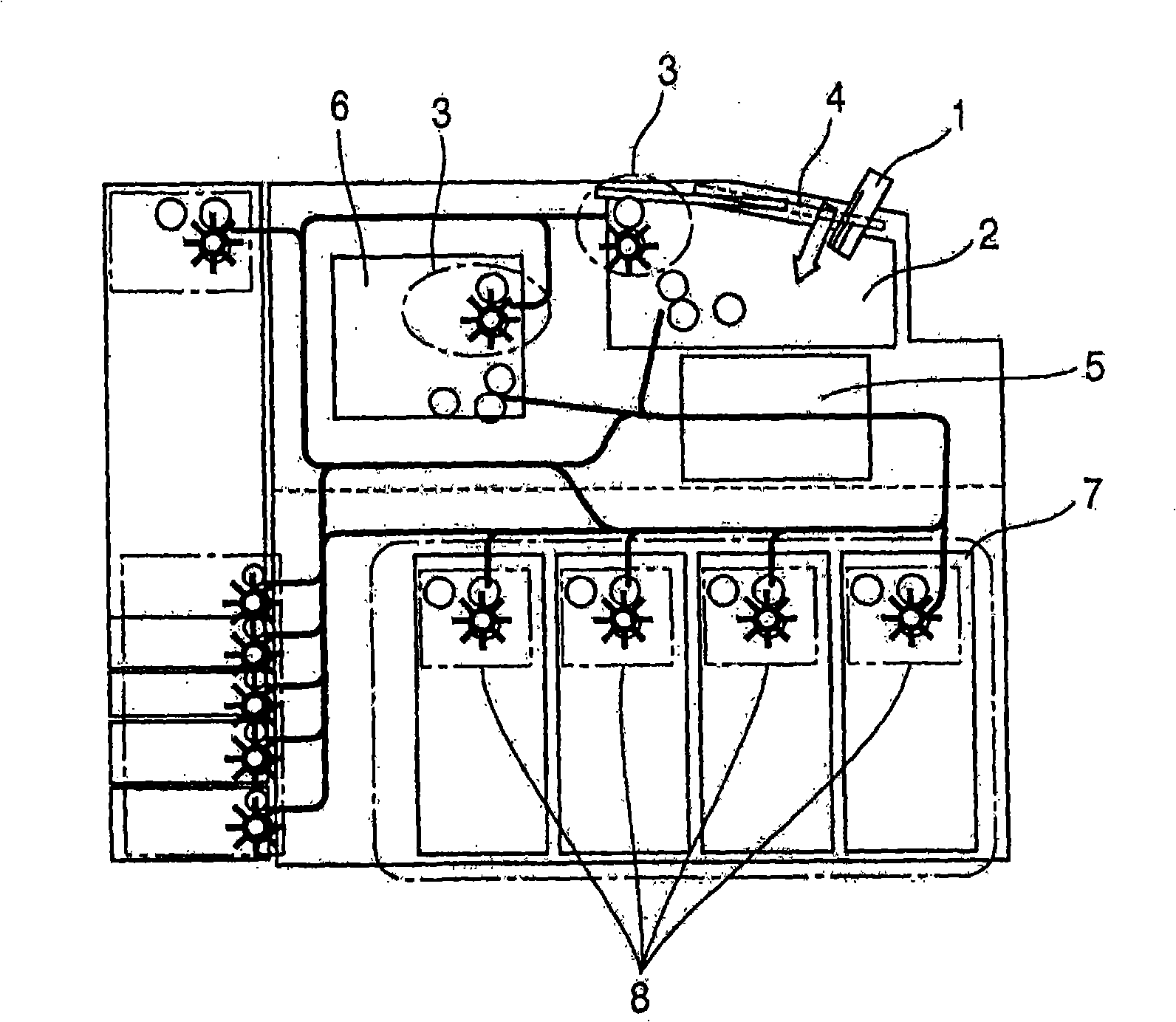
[0056] figure 1 It is a block diagram showing the banknote automatic teller machine of an embodiment.

[0057] In the figure, when the shutter 4 of the deposit and withdrawal port 2 is opened and the banknote 1 is inserted, the insertion is confirmed by a sensor in the deposit and withdrawal port (not shown), and the shutter 4 is closed.

[0058] Thereafter, the banknotes are separated one by one in the separating unit. After the separation, the banknotes 1 are discriminated by the identifying unit 5 , transported to the temporary storage unit 6 , and stacked in the stacking unit 3 . The temporary storage unit 6 and the deposit and withdrawal port 2 have the same separation part although the accumulation port and the separation port are different.

[0059] The banknotes 1 are separated one by one from the separation unit, and the denomination of the banknotes is discriminated in the identification unit 5 , and are transported to each banknote storage unit 7 through a not-sho...

Embodiment 2

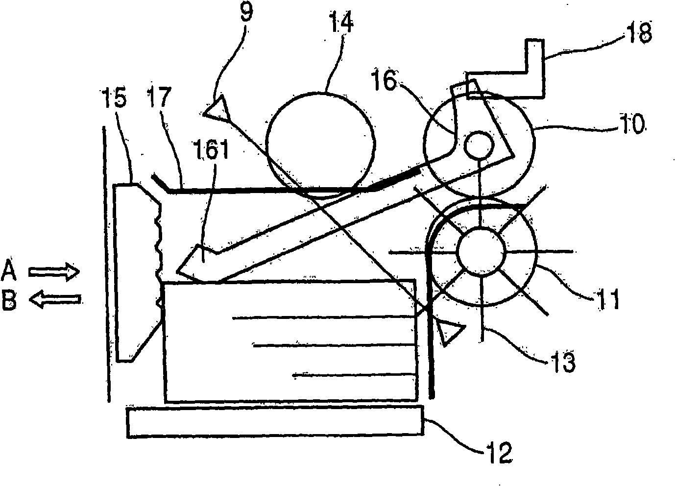
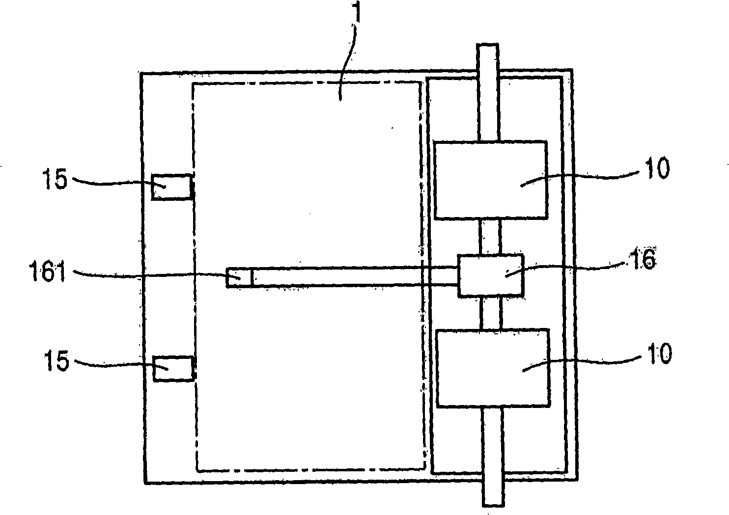
[0073] This embodiment has the same structure as the first embodiment above, and when the banknote is stuck at the banknote stopper 15 , the stuck state can be released by using the banknote presser 17 .

[0074] use Figure 5 The action flow will be described.

[0075] The number of passing sheets is counted by a sensor provided at an unillustrated discharge port (S1-1).

[0076] When the specified number of sheets has been piled up (passed) (S1-2), the detection of the position detection sensor 18 (S1-3) is implemented, and when it is connected for a certain period of time, as Figure 6 As shown, it is judged that the front end 161 of the stacking lever 16 is higher than the normal upper surface position due to the stacked banknotes caught in the banknote stopper 15, and the stacking is stopped (S1-4). Go to (S1-6) in case of disconnection.

[0077] Therefore, if Figure 7 , Figure 8 As shown, the banknote presser 17 is descended and raised, and the jamming of the accu...

Embodiment 3

[0083] This embodiment also has the same structure as the first embodiment above, and when the front end of the banknote is stuck at the banknote stopper 15 , the stuck state can be released by using the banknote presser 17 .

[0084] use Figure 9 The action flow will be described.

[0085] The number of passing sheets is counted by a sensor provided at an unillustrated discharge port (S2-1).

[0086] When the prescribed number of sheets has been piled up (passed) (S2-2), it is confirmed that each sensor is turned on (S2-3) under both conditions of the position detection sensor 18 and the upper surface detection sensor 9. When connected ( Figure 10 ), just stop stacking (S2-4), carry out the implementation of descending→rising of banknote presser 17, and release the blocking of stacked banknotes at banknote stopper 15 places (S2-5).

[0087] In the above (S2-3), in the case where only the position detection sensor 18 is turned on ( Figure 11 ), the upper surface detecti...


PUM


Abstract

The invention discloses a paper currency automatic teller with an accumulating part. The accumulating part has a paper currency stopper for preventing the paper currency being sent to the working table and an accumulating rod for pressing the paper currency sent to the working table orderly. The accumulating part is collocated with a paper currency presser for pressing the accumulated paper currency at the upper part; the upper surface detection sensor is used for detecting the upper surface height of the accumulated paper currency; in the paper currency automatic teller, sometimes the front end of the accumulated paper currency is blocked at the paper currency stopper, even if the working table declines, the paper currency will not be relieved; clearance is generated between the blocked paper currency and the accumulated paper currency, the invention has the adverse problem that the paper currency is vertically accumulated in the clearance. The invention is set with a location detection sensor when the accumulating rod reaches the prescribed angle, through making the front end of the accumulating rod located near the paper currency stopper to detect the condition of the paper currency locked at the paper currency stopper.

Description

technical field [0001] The present invention relates to a banknote automatic teller machine that is installed in financial institutions such as banks and post offices, and stores such as convenience stores, has a banknote storage unit, and delivers banknotes stored in the banknote storage unit one by one. Background technique [0002] In the existing automatic teller machine for banknotes, one or multiple banknotes are inserted from the deposit port, and when multiple banknotes are inserted, the separating part separates them one by one, and the inserted banknotes are transported to the identification part. It is judged to be true or false, and when it is judged to be a genuine banknote, it is transported to the temporary storage department. [0003] After the transaction is confirmed, the banknotes are separated one by one from the separation unit, the currency type is discriminated by the identification unit, and the banknotes are transported to each banknote storage unit ...

Claims


Application Information

Patent Timeline
Patent Type & Authority Applications(China)
IPC IPC(8): G07D11/00B65H31/00B65H31/26B65H31/18B65H43/06B65H29/20
CPCG07D2211/00G07F19/209
Inventor 冈田隆司
Owner OKI ELECTRIC IND CO LTD
Why Eureka
Try Eureka