

Retracting device
A tension spring, stop position technology, applied in furniture parts, home utensils, drawers, etc., can solve the problem of expensive pull-back automatic devices, and achieve the effect of compact structure
- Summary
- Abstract
- Description
- Claims
- Application Information
AI Technical Summary
Problems solved by technology
Method used
Image

Examples
Embodiment Construction
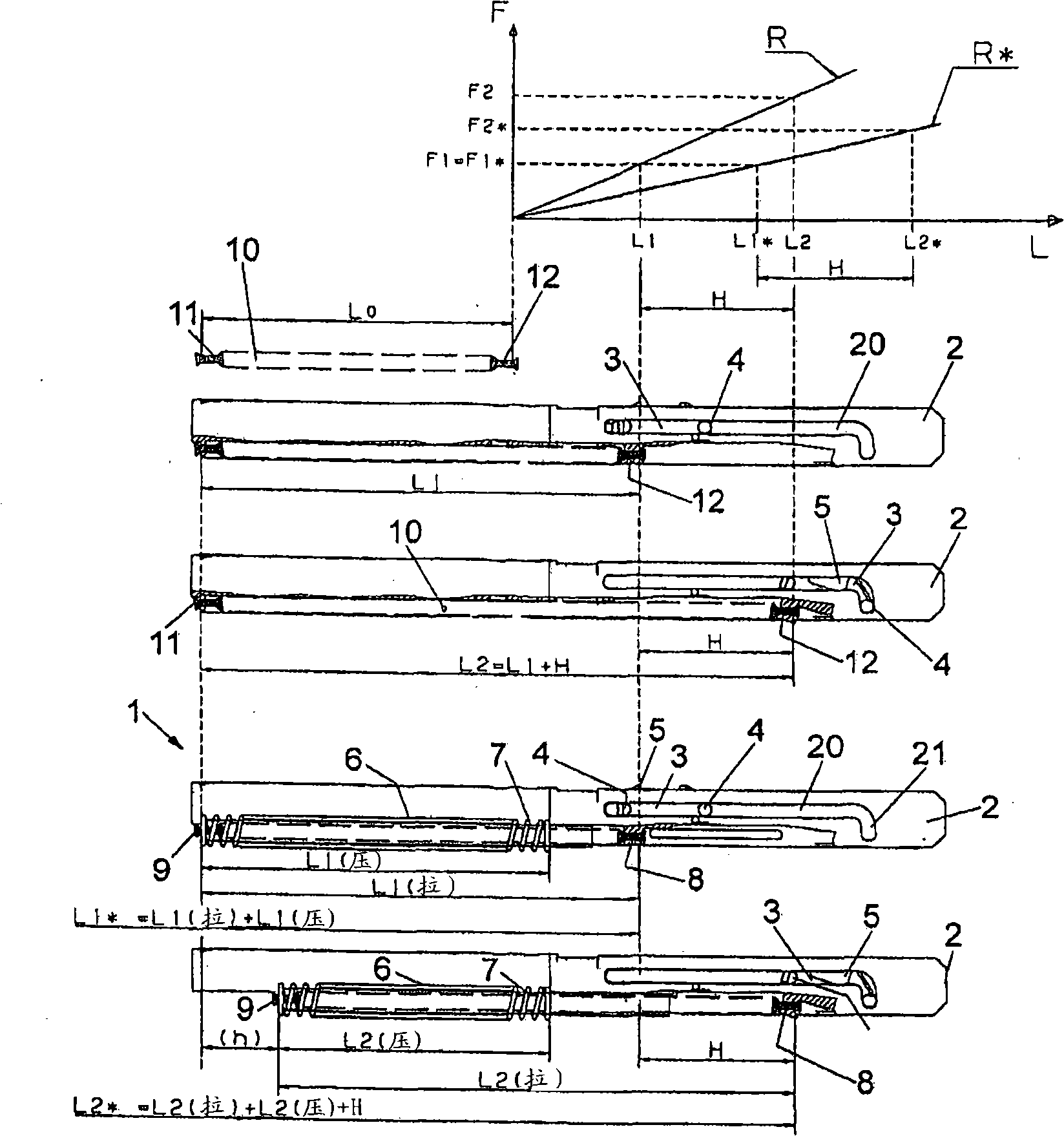
[0018] one in figure 1 The retraction device 1 shown in the lower region of , comprises a housing 2 which can be mounted on a furniture cabinet or on a fixed rail of the extension guide. A curve guide 20 with a curved end section 21 is formed in the housing 2 . A driver 3 is guided in the curve guide 20 and has two pins 4 which engage in the curve guide 20 . A recess 5 is formed on the carrier 3 for a trigger which can be inserted into the recess 5 in order to couple the carrier 3 to a movable furniture part in the region of the curve guide 20 .
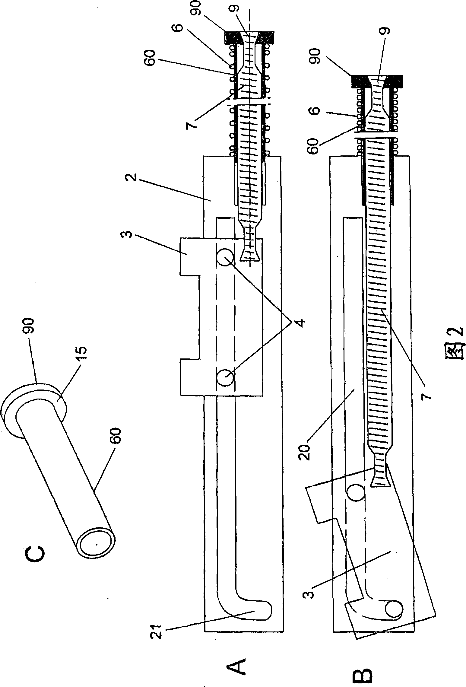
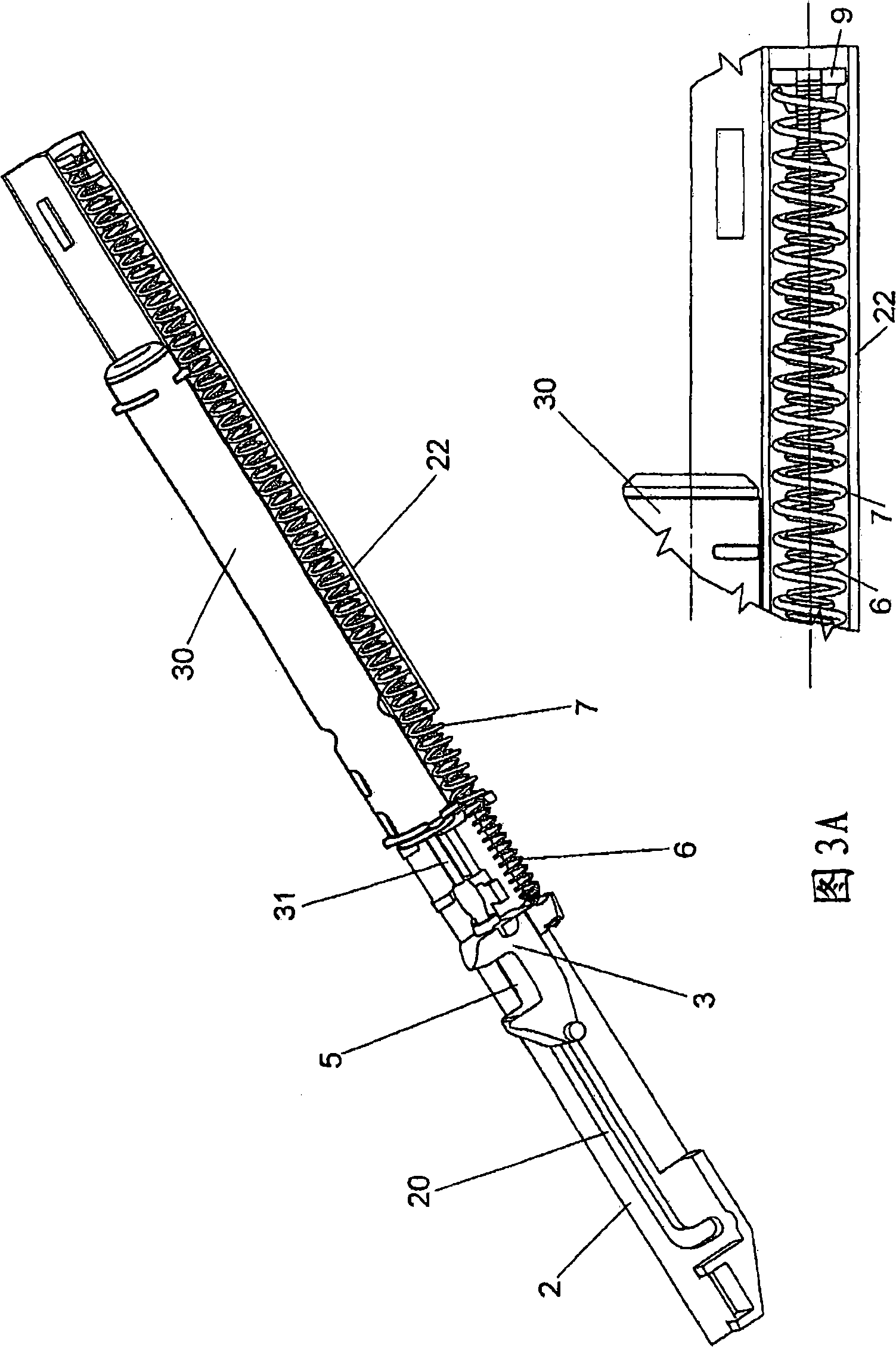
[0019] The driver 3 is pretensioned to the left by a compression spring 6 and a tension spring 7 . The compression spring 6 is supported on one side of the housing 2 and is coupled on the opposite side to a connecting piece 9 which in turn is connected to the tension spring 7 . The tension spring 7 is connected to the connecting part 8 with the driver 3 on the side opposite the connecting part 9 .
[0020] figure 1 The upper two...
PUM
 Abstract
Description
Claims
Application Information