
Valve assembly for injection valve and injection valve

A technology of valve components and injection valves, which is applied in the field of fuel injection valves and solenoid injection valves, and can solve the problems of reducing the guide length of valve needles, functional problems, wear, etc.

Active Publication Date: 2020-01-21
VTESCO TECH GMBH
View PDF4 Cites 0 Cited by
  • Summary
  • Abstract
  • Description
  • Claims
  • Application Information

AI Technical Summary

Problems solved by technology

However, this reduces the guide length of the valve needle and can lead to functional problems and wear

Method used


Image

  • Valve assembly for injection valve and injection valve
  • Valve assembly for injection valve and injection valve

Examples


Embodiment Construction

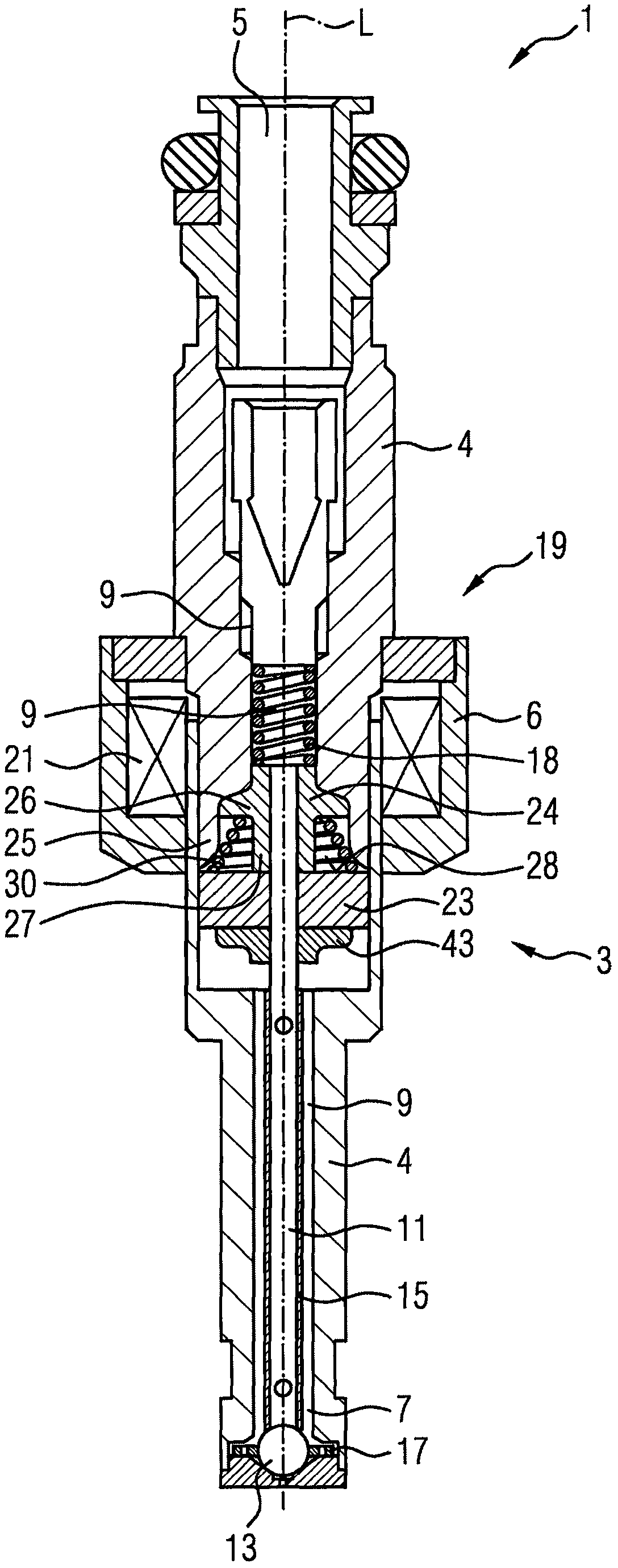
[0028] figure 1 Shown is an injection valve 1 which is particularly suitable for supplying fuel to an internal combustion engine. Injection valve 1 comprises in particular a valve assembly 3 . Said valve assembly 3 comprises a valve body 4 having a central longitudinal axis L. As shown in FIG. The housing 6 is partially disposed around the valve body 4 .

[0029] The valve body 4 includes a cavity 9 . The cavity 9 has a fluid outlet portion 7 . The fluid outlet portion 7 communicates with the fluid inlet portion 5 provided in the valve body 4 . The fluid inlet portion 5 and the fluid outlet portion 7 are in particular located at opposite axial ends of the valve body 4 . The cavity 9 receives the valve needle 11 . The valve needle 11 includes a needle shaft 15 and a sealing ball 13 welded to the tip of the needle shaft 15 .

[0030] In the closed position of the valve needle 11 it rests sealingly against a seat plate 17 with at least one injection nozzle. A preloaded ca...


PUM


Abstract

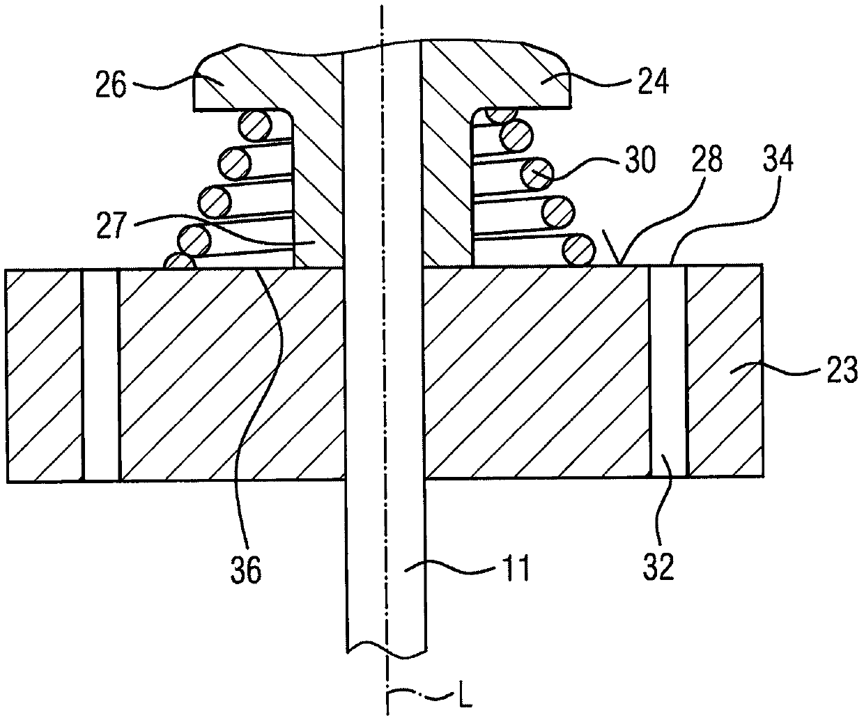
The invention discloses a valve assembly for an injection valve and an injection valve. The disclosed valve assembly (3) for an injection valve (1) comprises a valve body (4) having a cavity (9), a valve needle (11) movable axially in the cavity (9), an armature ( 23), the valve needle (11) is fixedly connected to the retaining element (24), which extends in the radial direction and is arranged in the axial region of the valve needle (11) facing away from the fluid outlet portion (7) , the armature (23) can slide on the valve needle (11) and acts on the valve needle (11) via the retaining element (24). A conical spring (30) is disposed between the retaining element (24) and the top side (28) of the armature (23) facing the retaining element (24), thereby biasing the armature (23) away from the retaining element (24).

Description

technical field [0001] The present disclosure relates to a valve assembly for an injection valve and an injection valve, eg, a fuel injection valve for a vehicle. The present disclosure relates specifically to solenoid injection valves. Background technique [0002] Such injection valves must be able to supply fluid even at high fuel pressures. One design that ensures this is the "free-lift" design. According to this design, the armature of the electromagnetic actuator unit travels through about a "pre-travel gap" before it engages the valve needle to open the injector. Therefore, kinetic energy is accumulated before actually opening. [0003] The "free lift"-concept uses a so-called free lift spring which biases the armature away from the upper retaining element fixed to the valve needle. When the actuator unit is energized, the armature travels against the load of this spring before engaging the upper retaining element to move the valve needle. In general, the farther...

Claims


Application Information

Patent Timeline
Patent Type & Authority Patents(China)
IPC IPC(8): F02M51/06F02M61/10F02M61/16
CPCF02M51/066F02M2200/50F02M51/061F02M61/10F02M51/0625F02M61/20
Inventor F·法拉斯基C·哈曼L·马尔基
Owner VTESCO TECH GMBH
Learn More