Stapler

A stapler and sensor technology, which is applied to staple staple tools, staple tools, manufacturing tools, etc., can solve problems such as inability to bind paper, and achieve neat binding positions, stable binding, and good binding quality.

Inactive Publication Date: 2008-10-08
MAX CO LTD
View PDF4 Cites 2 Cited by
  • Summary
  • Abstract
  • Description
  • Claims
  • Application Information

AI Technical Summary

Problems solved by technology

In this case, the result is that the paper cann

Method used


Image

  • Stapler
  • Stapler
  • Stapler

Examples


Embodiment 1

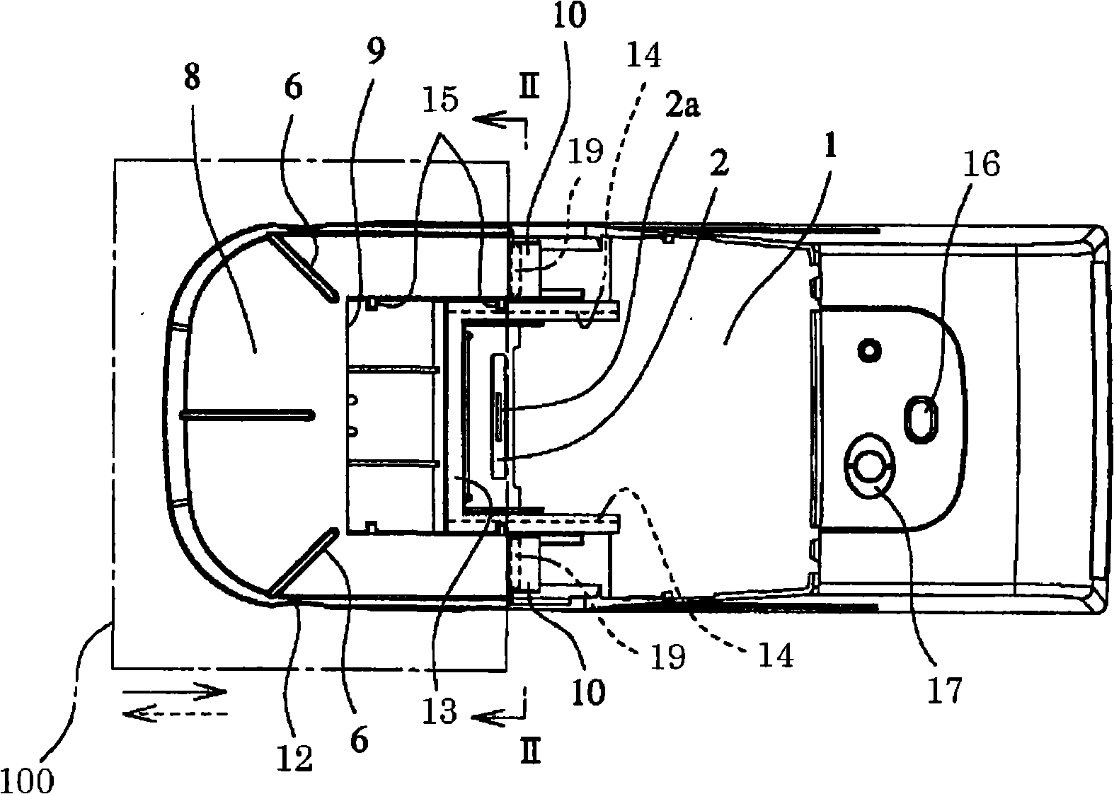
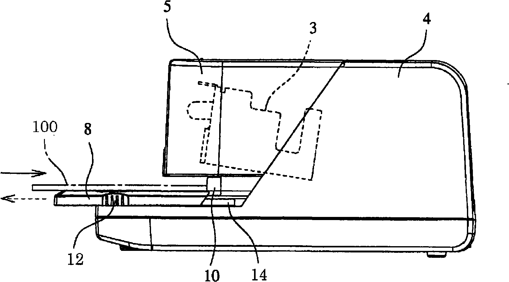
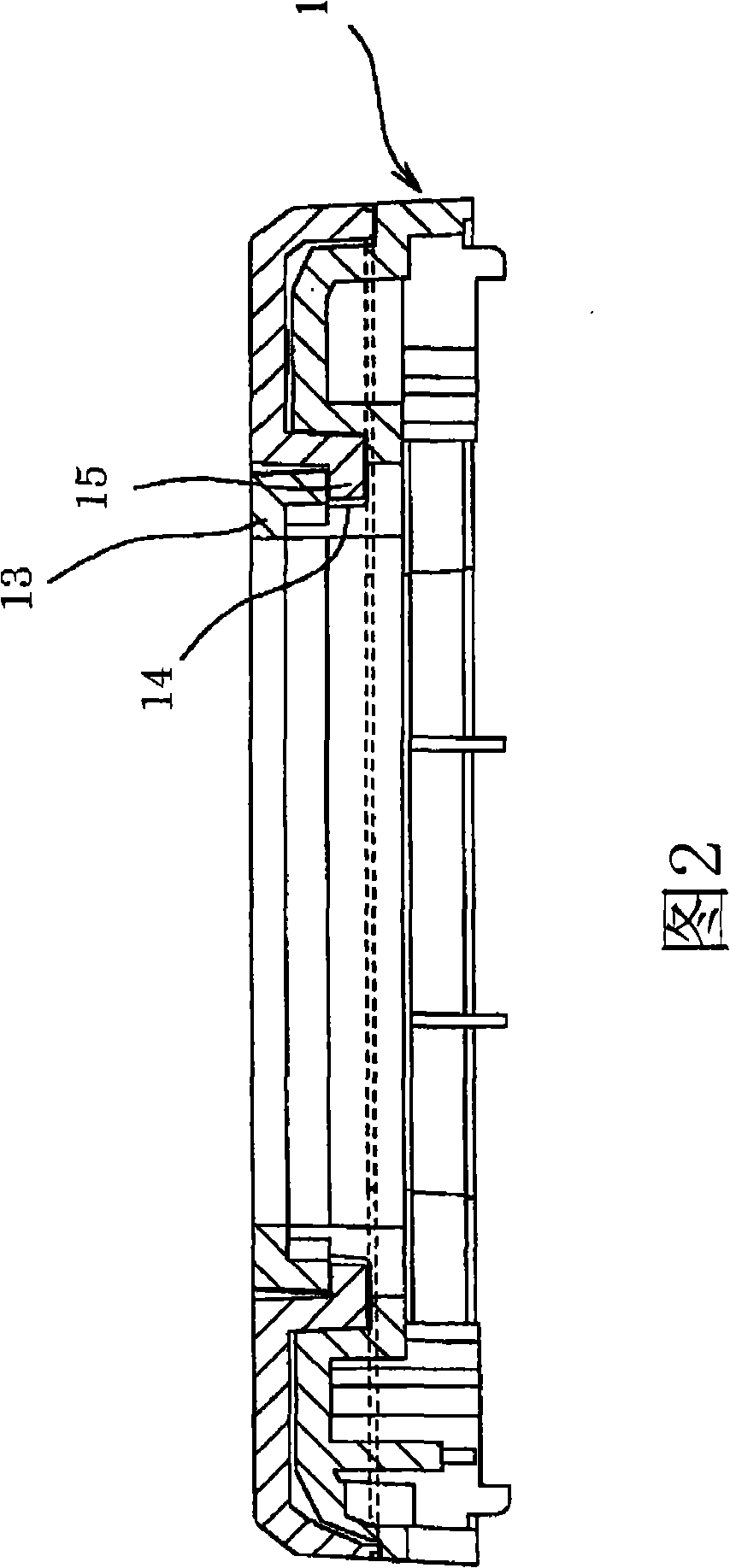
[0050] Such as Figure 1A , Figure 1B As shown, the electric stapler in Embodiment 1 includes a binding table 1 provided with a stapling component 2 ; The sheets 100 are inserted between the stapling member 2 and the staple driving unit 3 to be bound. The upper rear half of the binding table 1 and the output unit 3 are covered by covers 4 , 5 .

[0051] The staple driving unit 3 has a staple driving mechanism that drives a driving plate that drives staples. This driving mechanism is operated by an electric motor, and drives the leading staple in the driving unit 3 downward. The driven staple penetrates the paper 100 and is bent in contact with the binding groove 2 a of the binding member 2 to bind the paper 100 .

[0052] A movable stage 8 is provided on the front half of the binding table 1 . The movable stage 8 is a member on which paper 100 is placed, and its upper part has the same shape as that of the binding table 1 . A concave portion 9 is formed inside the movabl...

Embodiment 2

[0062] Figure 6A is a plan view of the electric stapler in the second embodiment, Figure 6B yes Figure 6A side view. Furthermore, the section VII-VII of FIG. 6 is shown in FIG. 7 . In the second embodiment, the same components as those in the first embodiment are assigned the same reference numerals, and descriptions thereof are omitted.

[0063] In the electric stapler of the second embodiment, a paper detection sensor 20 is provided to face the recessed portion 9 formed in the rear portion of the movable stage 8 . The paper detection sensor 20 is guided by the guide rail 18, which can slide in and out of the paper 100 in the insertion and withdrawal direction (front and back direction) of the paper 100 in such a way that it can enter and exit freely relative to the concave portion 9, wherein the guide rail 18 is provided on the binding member 2 having the binding groove 2a. The rear part is arranged on the top of the binding table 1, and extends a predetermined length...


PUM


Abstract

A stapler comprising a stapling table, a clinch member provided on the stapling table, a staple driving unit provided above the stapling table, and a movable stage provided to be able slide with respect to the stapling table. An engaging unit is formed on the movable stage to position the edges of sheets placed on the movable stage. The sheets are stapled by being inserted between the clinch member and the staple driving unit.

Description

technical field [0001] The invention relates to a stapler, which has a movable stage for placing paper, and the movable stage is slid corresponding to the binding position of the paper to perform binding. Background technique [0002] In order to adjust the staple driving position of the paper, there are following electric staplers: the binding position adjustment sensor with an automatic switch is moved along the insertion and extraction direction of the paper to adjust the binding position (for example, refer to Japanese Patent Laying-Open 7-290373 Bulletin). [0003] In addition, there is also an electric stapler in which an automatic switch and a manual switch are provided in parallel (for example, refer to Japanese Patent Application Publication No. 6-45340). [0004] In addition, there is also an electric stapler in which a positioning member is slidably provided in the paper insertion and withdrawal direction, and the positioning member abuts on the end of the paper ...

Claims


Application Information

Patent Timeline
IPC IPC(8): B25C7/00B25C5/15
Inventor 加藤裕齐藤智亮
Owner MAX CO LTD
Why Eureka
Try Eureka