
Automatic paper angle bead binding device

A technology of automatic binding and paper corner protection, applied in packaging, papermaking, transportation and packaging, etc., can solve the problems of single function, low work efficiency, slow speed, etc., and achieve the effect of high degree of automation, improved efficiency and convenient operation

Pending Publication Date: 2022-02-08
青岛强之力工贸有限公司
View PDF1 Cites 0 Cited by
  • Summary
  • Abstract
  • Description
  • Claims
  • Application Information

AI Technical Summary

Problems solved by technology

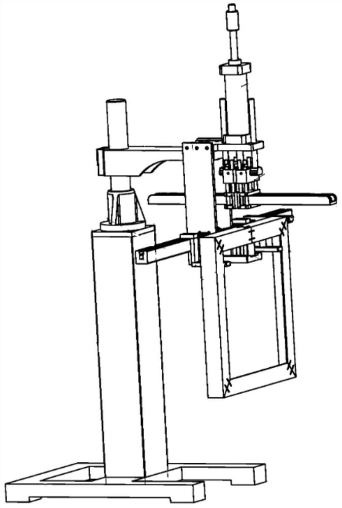
[0003] At present, the paper corner protector binding machines on the market are simple in structure and single in function, and can only punch out one nail at a time. figure 2 The pneumatic paper corner frame nailing forming machine shown includes a bracket, a nailing device and an auxiliary nailing device, which can only handle one mounting position on one side of a paper corner at a time. Therefore, it is necessary to rotate the paper corner The method of transferring the position to be assembled to the staple module for binding can be completed several times in succession to complete the binding of a paper corner. The working efficiency of this device is low and the speed is slow.

Method used


Image

  • Automatic paper angle bead binding device
  • Automatic paper angle bead binding device
  • Automatic paper angle bead binding device

Examples


Embodiment 1

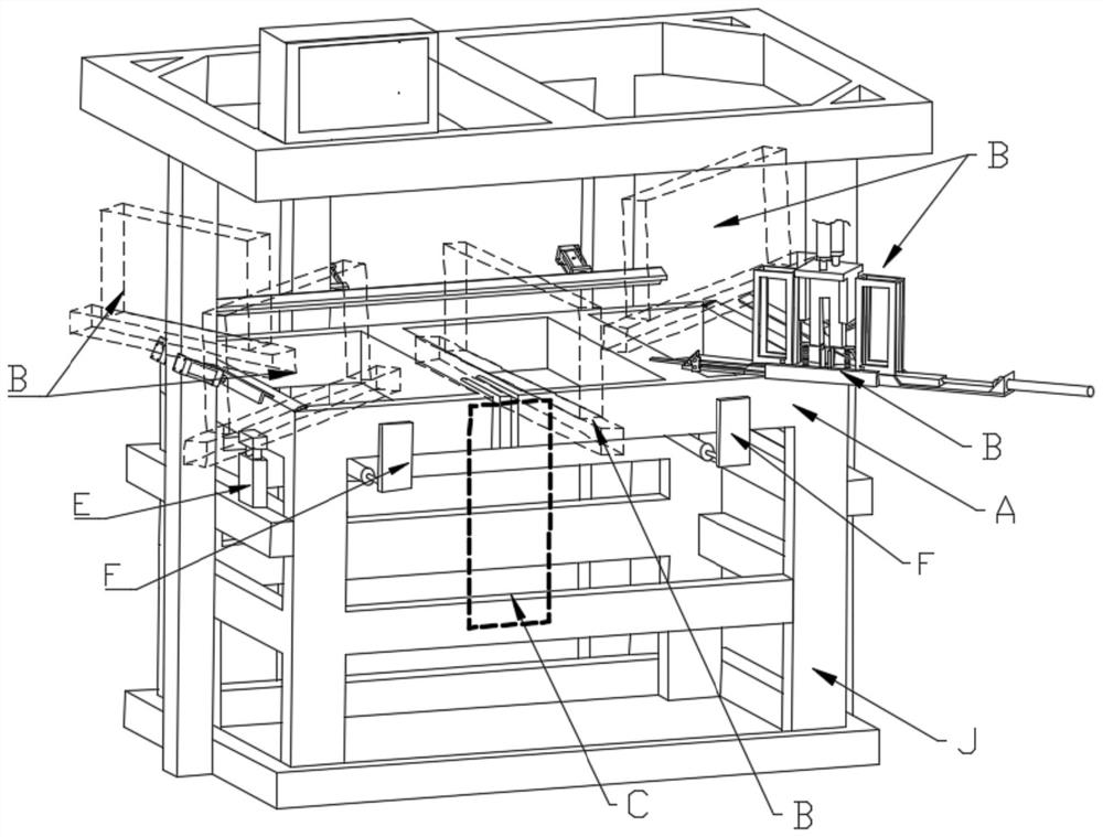
[0053] Such as image 3 As shown, this embodiment provides an automatic paper corner binding device, which includes a paper corner positioning platform A that is horizontally arranged on the frame J and is consistent with the shape of the paper corner after forming, and is installed on the paper corner positioning platform. A plurality of paper corner protection horizontal binding mechanisms B arranged on the same horizontal plane above the binding position, at least one set of paper corner protection side binding mechanisms arranged on the side of the paper corner protection positioning platform and used for binding the side of the paper corner protection at the side where the head and tail overlap c.

[0054] When working, all the paper corner horizontal binding mechanism B simultaneously binds all the binding positions on the upper surface of the paper corner, and the paper corner side binding mechanism C binds the side of the paper corner, through the above two kinds of bi...


PUM


Abstract

The invention discloses an automatic paper angle bead binding device. The device comprises a paper angle bead positioning table which is horizontally arranged on a rack and is consistent with a formed paper angle bead in shape, horizontal paper angle bead binding mechanisms which are mounted over a binding part of the paper angle bead positioning table and are positioned on the same horizontal plane, at least one paper angle bead lateral binding mechanism which is arranged on the side face of the paper angle bead mounting and positioning table and used for binding the side faces of the end-to-end overlapping positions of the paper angle beads; the paper angle bead horizontal binding mechanism comprises a horizontal base and two paper angle bead binding assemblies arranged on the left side and the right side of the center of the horizontal base respectively; the two paper angle bead binding assemblies are arranged in opposite directions; and the paper angle bead lateral automatic binding mechanism comprises a longitudinal base connected to the side face of the rack and a paper angle bead binding assembly vertically arranged on the longitudinal base. The automatic paper angle bead binding device is exquisite in structural arrangement and convenient to operate, binding of all positions can be achieved in one step, and the automation degree and the working efficiency are greatly improved.

Description

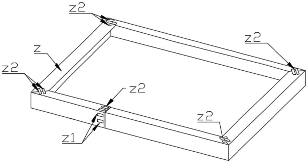
technical field [0001] The invention relates to the technical field of paper corner protection processing equipment, in particular to an automatic paper corner protection binding device. Background technique [0002] With the rapid development of the packaging industry, the application of paper corner protectors to strengthen cartons and other packaging is becoming more and more common. At the same time, people have higher requirements for the strength of paper corner protectors. There are many types of paper corner protectors. One of the common types is square-shaped paper corner protectors. This kind of paper corner protectors is usually made of strips of cardboard folded multiple times to form a rectangular shape, and the overlap between the end and the end and the corner Binding is carried out, and finally formed as figure 1 The rectangular paper frame shown. The above-mentioned box-shaped paper corner Z usually needs to drive two nails into the four corner binding pos...

Claims


Application Information

Patent Timeline
IPC IPC(8): B31B50/68B31B50/02B31B50/74B65D6/00B65D25/00
CPCB31B50/68B31B50/74B31B50/02B65D25/00B65D13/04
Inventor 姜善磊
Owner 青岛强之力工贸有限公司
Learn More